Original Industrial Spare Part
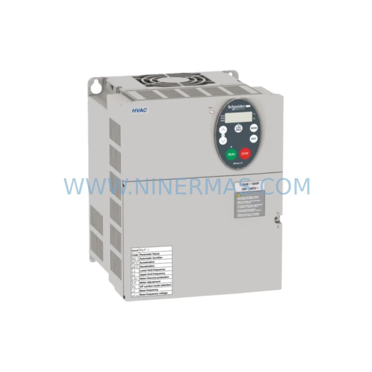
Schneider ATV21HD18N4 Retrofit-Compatible AC Drive for Legacy Systems
Verify the part, confirm the platform family, and move straight into quotation with the right commercial details.
RFQ Ready
- SKUATV21HD18N4
- CategoryPLC & Industrial Automation Modules
- BrandSchneider
- SupportAvailability, lead time, condition, and shipping coordination
How Buyers Usually Use This Page
- Confirm the exact part number and platform family before sending the quote request.
- Use direct email when quantity, condition, and destination are already defined internally.
- Switch to the broader brand or category archive when you need alternates nearby.
Series Navigation
Move through the most common platform families behind this part.
Product RFQ
Send this part directly for quotation.
Include quantity, required condition, destination country, and target delivery timing. Current reference: Schneider ATV21HD18N4 Retrofit-Compatible AC Drive for Legacy Systems with SKU ATV21HD18N4.
Schneider ATV21HD18N4 Retrofit-Compatible AC Drive: Seamless Legacy System Modernization
The Schneider Electric ATV21HD18N4 is a 18.5 kW (25 HP) three-phase 380–480 V AC variable frequency drive from the Altivar 21 series, purpose-built for HVAC and pump applications. As the Altivar 21 platform approaches end-of-life and spare parts become increasingly scarce, the ATV21HD18N4 remains one of the most sought-after retrofit and replacement units for engineers tasked with keeping legacy automation systems operational without a full control system overhaul.
At NINERMAS, we maintain verified stock of the ATV21HD18N4 to support planned maintenance windows, emergency breakdowns, and phased modernization projects across manufacturing plants, water treatment facilities, commercial HVAC installations, and process automation lines.
Upgrade Compatibility Table
| Parameter | ATV21HD18N4 Specification | Retrofit Notes |
|---|---|---|
| Power Rating | 18.5 kW / 25 HP | Verify motor nameplate before swap |
| Supply Voltage | 380–480 V AC, 3-phase | Confirm panel supply voltage tolerance |
| Output Frequency | 0.1–400 Hz | Check legacy drive parameter settings |
| Control Terminals | Logic inputs: 6 DI, 2 AO, 2 AI | Map terminal-by-terminal against old wiring diagram |
| Communication | Modbus RTU (optional CANopen) | Verify PLC communication card compatibility |
| Mounting | Panel mount, IP20 / UL Type 1 | Confirm DIN rail or back-panel clearance |
| Cooling | Forced air (internal fan) | Ensure cabinet ventilation meets derating specs |
| Replacement Path | Replaces earlier ATV21 variants | Parameter backup recommended before removal |
| Commissioning Tool | SoMove software / keypad | Use VW3A1101 programming keypad for on-site setup |
| Warranty | 12-Month Warranty | Covered by NINERMAS from date of shipment |
Retrofit Planning for Existing Automation Systems
Replacing an end-of-life or failed variable frequency drive in a live production environment requires careful pre-planning. When integrating the ATV21HD18N4 into an existing control cabinet, engineers should begin by auditing the available power supply capacity. The drive draws significant inrush current at startup, and the upstream circuit breaker or fused disconnect — often a legacy GV2ME or GV3ME motor circuit breaker — must be rated appropriately for the new unit’s input current.
Terminal wiring is the next critical step. The ATV21HD18N4 uses a standard Altivar terminal layout, but older installations may have been wired to an ATV11, ATV18, or early ATV21 variant with slightly different logic input assignments. Always cross-reference the original wiring diagram against the ATV21HD18N4 terminal block layout before energizing. Pay particular attention to the analog input configuration — AI1 and AI2 may need to be reconfigured from voltage to current mode depending on the existing speed reference signal from the Magelis XBTGT or XBTGK HMI panel.
For installations using a Modicon M340 or Modicon Premium PLC as the master controller, the Modbus RTU communication link between the PLC and the drive must be re-established after replacement. Confirm the slave address, baud rate, and parity settings match the original drive configuration. If the legacy system used a TSX SCY 21601 serial communication module, ensure the new drive’s Modbus parameters are aligned before going live.
Backplane and rack space should also be verified. In compact control cabinets, the ATV21HD18N4’s physical dimensions (height, width, depth) must be confirmed against the available mounting space. If the cabinet also houses an ATV312 or ATV320 for auxiliary motor control, ensure adequate thermal separation and airflow between drives. A VW3A9525 line choke or VW3A4601 EMC filter may be required to meet site electromagnetic compatibility requirements, particularly in sensitive process environments.
I/O expansion requirements should be reviewed as part of the retrofit scope. If the original system relied on a discrete I/O module such as a TM3DI16 or TM3DQ16R for additional digital signals, confirm that the new drive’s onboard I/O is sufficient or that the expansion module remains compatible with the updated control logic. Module addressing in the PLC program may need to be adjusted if the drive’s network node address changes during replacement.
Before final commissioning, upload the motor parameters — rated voltage, rated current, rated frequency, rated speed, and motor cos φ — into the ATV21HD18N4 using the VW3A1101 remote keypad or SoMove PC software. Run an auto-tune sequence with the motor disconnected from the load where possible to optimize flux and torque control. Verify that all HMI screens referencing drive status words, fault codes, and speed feedback are displaying correctly before returning the system to production.
Downtime Control During System Migration
Minimizing unplanned downtime is the primary concern for any maintenance team executing a VFD replacement. For the ATV21HD18N4, a well-prepared retrofit can typically be completed within a single planned maintenance window of 4–8 hours, provided all materials — including the replacement drive, wiring adapters, and commissioning tools — are on-site before the shutdown begins.
Begin by backing up the existing drive’s parameter set using SoMove or the keypad before powering down. This preserves the original motor tuning data, ramp times, speed references, and fault history, which can be invaluable for troubleshooting if the new drive behaves unexpectedly during initial startup. If the original drive has already failed and parameter backup is not possible, reconstruct the parameter set from the original commissioning report or the motor nameplate data.
Isolate the drive from the supply using the upstream isolator or circuit breaker and verify that DC bus voltage has discharged fully before opening the cabinet — typically a minimum of 5 minutes after power-off. Label all control wiring before disconnection to prevent miswiring during reinstallation. Use the original wiring diagram as the reference, and photograph the terminal block before removal as an additional safeguard.
After physical installation, perform a continuity check on all power and control connections before energizing. Apply power and verify that the drive powers up without fault. Enter the motor parameters, set the speed reference source, and configure the communication address before enabling the run command. Perform a no-load test run at low speed to confirm direction of rotation and speed reference response before reconnecting the mechanical load. Document all final parameter settings and update the cabinet wiring diagram to reflect the new installation.
By following this structured approach, most ATV21HD18N4 retrofit projects can be completed with zero unplanned production loss, protecting both the process continuity and the maintenance team’s credibility with plant management.
Retrofit Support FAQ
Q1: Is the ATV21HD18N4 a direct drop-in replacement for earlier Altivar 21 models?
A: The ATV21HD18N4 is dimensionally and electrically compatible with other Altivar 21 18.5 kW variants. However, always verify the terminal layout and parameter set against the unit being replaced, as minor firmware and hardware revisions may affect specific functions.
Q2: Can I use the ATV21HD18N4 with my existing Modbus RTU network without additional hardware?
A: Yes. The ATV21HD18N4 supports Modbus RTU natively via its RJ45 port. No additional communication card is required for standard Modbus RTU integration with Modicon or third-party PLCs.
Q3: What pre-shipment testing does NINERMAS perform on the ATV21HD18N4?
A: Every unit undergoes power-on functional testing, parameter verification, and visual inspection before shipment. Units are shipped with original or equivalent packaging to prevent transit damage.
Q4: What does the 12-month warranty cover?
A: The 12-month warranty covers manufacturing defects and functional failures under normal operating conditions from the date of shipment. NINERMAS provides replacement or repair support for any unit that fails within the warranty period. Contact sale@ninermas.com for warranty claims.
| Product Series | Altivar |
|---|---|
| Country of Origin | FR |
Catalog Continuation
More Schneider modules in the catalog.
Use the brand lane to compare nearby part numbers, platform-adjacent modules, and other inquiry-ready listings before sending your final RFQ.
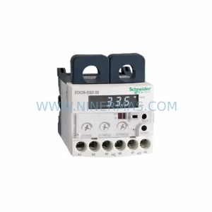
SKU: EOCR-SSD 05 EOCRSSD-05DF7
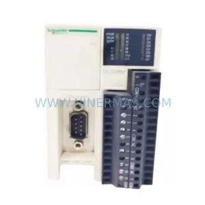
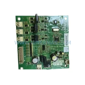
Schneider EOCR-SSD 05 Safety-Reliable Motor Relay for Critical Control
Catalog Continuation
Alternative parts within PLC & Industrial Automation Modules.
Stay inside the same system family when you need substitutes, adjacent modules, or a broader shortlist for procurement review.
SKU: 6SL3224-0BE33-7UA0
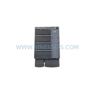
Siemens 6SL3224-0BE33-7UA0 Service-Ready Spare Part
SKU: HENF331395R0001 P4LDA
ABB HENF331395R0001 Service-Ready Industrial Spare Part