Original Industrial Spare Part
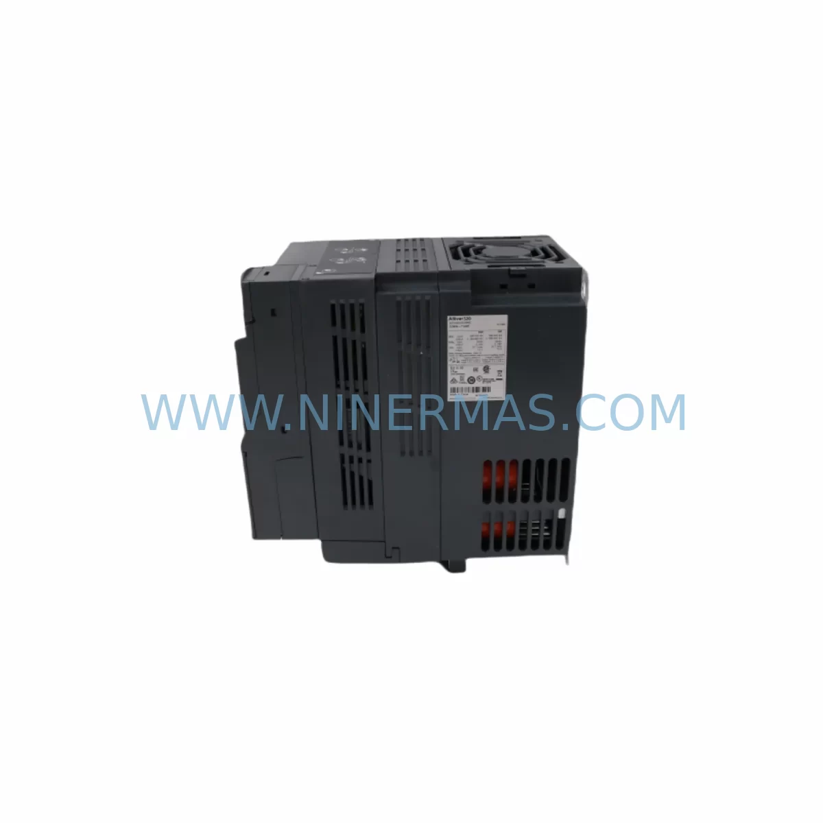
Schneider ATV320U55N4B Retrofit-Compatible Variable Speed Drive
Verify the part, confirm the platform family, and move straight into quotation with the right commercial details.
RFQ Ready
- SKUATV320U55N4B
- CategoryPLC & Industrial Automation Modules
- BrandSchneider
- SupportAvailability, lead time, condition, and shipping coordination
How Buyers Usually Use This Page
- Confirm the exact part number and platform family before sending the quote request.
- Use direct email when quantity, condition, and destination are already defined internally.
- Switch to the broader brand or category archive when you need alternates nearby.
Series Navigation
Move through the most common platform families behind this part.
Product RFQ
Send this part directly for quotation.
Include quantity, required condition, destination country, and target delivery timing. Current reference: Schneider ATV320U55N4B Retrofit-Compatible Variable Speed Drive with SKU ATV320U55N4B.
Schneider ATV320U55N4B Retrofit-Compatible Variable Speed Drive for Legacy Systems
The Schneider ATV320U55N4B is a 5.5 kW (7.5 HP) three-phase variable speed drive from the Altivar 320 series, engineered for seamless integration into aging automation infrastructure. Rated at 400–480 V AC input, this drive is purpose-built to replace discontinued ATV31 and ATV312 series units without requiring full panel redesign or PLC reprogramming. For maintenance engineers managing legacy motor control centers, the ATV320U55N4B delivers a controlled, low-risk migration path that preserves existing wiring topology, terminal assignments, and communication architecture.
Industrial facilities operating aging variable speed drive fleets face compounding risks: discontinued spare parts, obsolete firmware, and incompatible communication stacks. The ATV320U55N4B addresses these challenges directly. Its compact bookshelf form factor fits standard DIN rail and panel mounting configurations used across legacy Schneider control cabinets, and its native Modbus RTU and CANopen communication support ensures compatibility with existing SCADA, PLC, and HMI architectures without protocol gateway additions.
Before committing to a retrofit, engineers should verify several critical parameters: available power supply capacity in the control cabinet (the ATV320U55N4B draws up to 14.3 A at 400 V), terminal block pitch compatibility with existing cable lugs, backplane clearance for heat dissipation (minimum 50 mm side clearance recommended), and the drive’s I/O address mapping relative to the legacy unit being replaced. If the original drive used analog speed reference via 0–10 V or 4–20 mA signals, these are fully supported on the ATV320U55N4B’s AI1 and AI2 terminals — no signal conditioning or isolation relay changes are required in most standard configurations.
Program logic compatibility is a frequent concern during ATV31 or ATV312 replacement. The ATV320 series uses a parameter structure that is largely consistent with its predecessors, and Schneider’s SoMove configuration software supports parameter file migration from legacy drive configurations. Engineers should audit motor nameplate data, acceleration/deceleration ramp settings, and fault response parameters before commissioning. Where the original drive used a Modbus RTU network, the ATV320U55N4B retains the same register map structure for standard control words and status words, minimizing PLC program changes.
Upgrade Compatibility Table
| Parameter | Legacy ATV31 / ATV312 | ATV320U55N4B (Replacement) | Retrofit Notes |
|---|---|---|---|
| Power Rating | 5.5 kW / 7.5 HP | 5.5 kW / 7.5 HP | Direct power-class match |
| Input Voltage | 380–480 V AC, 3-phase | 380–480 V AC, 3-phase | No transformer required |
| Communication | Modbus RTU / CANopen | Modbus RTU / CANopen | Same register map; verify baud rate |
| Analog Inputs | 0–10 V / 4–20 mA | 0–10 V / 4–20 mA (AI1, AI2) | No signal isolator change needed |
| Digital I/O | 6 DI / 2 DO | 6 DI / 3 DO | Additional DO available; verify wiring |
| Mounting Style | Bookshelf / DIN Rail | Bookshelf / DIN Rail | Confirm panel depth clearance |
| Protection Rating | IP20 | IP21 | Improved ingress protection |
| Configuration Tool | PowerSuite / SoMove | SoMove / DTM | Parameter migration supported |
| Warranty | OEM EOL — no coverage | 12-Month Warranty | Covered from shipment date |
Retrofit Planning for Existing Automation Systems
A successful ATV320U55N4B retrofit begins with a full audit of the existing control cabinet. Engineers should document the current drive’s terminal wiring diagram, including power terminals (R/S/T input, U/V/W motor output), brake resistor connections if fitted, and all control wiring to the terminal block. In many legacy installations, the ATV31C055N4 or ATV312HU55N4 will have been wired with a dedicated 24 V DC logic supply — the ATV320U55N4B supports the same 24 V external logic supply configuration, ensuring uninterrupted control circuit continuity during the swap.
For installations where the legacy drive is networked via a VW3A3608 Modbus/CANopen communication card, engineers should note that the ATV320 series integrates these protocols natively without an add-on card, simplifying the cabinet layout and reducing potential failure points. If the existing system uses a Modicon M340 or Modicon M580 PLC as the network master, the ATV320U55N4B’s Modbus RTU slave implementation is fully compatible with standard Unity Pro or EcoStruxure Control Expert function blocks used for drive control.
I/O expansion requirements should also be assessed at the planning stage. If the legacy system relied on a TM3DI16 digital input expansion module or a TM3AQ4 analog output module connected to the PLC rack, these remain unaffected by the drive replacement — the ATV320U55N4B interfaces directly with the PLC’s existing I/O map. Where the control cabinet includes a Magelis HMIGTO or HMISTO HMI panel, existing drive monitoring screens referencing Modbus register addresses will continue to function without screen redesign, provided the Modbus node address and baud rate are matched to the legacy configuration.
Power supply integrity is critical. Before installation, verify that the cabinet’s ABL8REM24030 or equivalent 24 V DC power supply has sufficient residual capacity to support the ATV320U55N4B’s control circuit load. Inspect the incoming line reactor or EMC filter — if a VW3A4401 line filter was fitted to the original drive, it remains compatible and should be retained to maintain EMC compliance. Brake resistor assemblies, if present, should be re-evaluated against the ATV320’s braking transistor specifications before reconnection.
Installation space confirmation is a frequent bottleneck in legacy panel retrofits. The ATV320U55N4B measures 270 mm (H) × 105 mm (W) × 156 mm (D) — engineers should verify that the existing cutout or DIN rail section accommodates these dimensions, particularly in densely populated control cabinets where a Zelio Logic SR3B261BD smart relay, terminal blocks, or cable ducting may limit available depth. Pre-shipment functional testing is performed on all units prior to dispatch, and each ATV320U55N4B is supplied with a 12-month warranty covering manufacturing defects from the date of shipment.
Downtime Control During System Migration
Minimizing production downtime during a variable speed drive replacement requires structured pre-commissioning preparation. Before the maintenance window opens, engineers should complete a full parameter backup of the existing drive using SoMove or a handheld programming terminal such as the VW3A1006 remote keypad. This backup captures all motor parameters, ramp settings, PID configurations, and fault thresholds — providing a reference baseline for the ATV320U55N4B commissioning and a recovery point if unexpected behavior is observed during initial run.
The physical swap can typically be completed within 60–90 minutes for a standard bookshelf installation, assuming terminal wiring is pre-labeled and the replacement unit has been pre-configured offline using SoMove. Engineers should power down the cabinet via the main isolator, discharge the DC bus (allow a minimum of 15 minutes after power-off before touching power terminals), and photograph the existing terminal wiring before disconnection. Re-termination should follow the original wiring diagram, with particular attention to the motor thermistor input (PTC/NTC) and the safe torque off (STO) circuit if active safety functions were implemented on the legacy drive.
After physical installation, the initial power-up sequence should be performed with the motor disconnected where possible, allowing drive self-test and communication link verification before applying load. Confirm that the Modbus node address, baud rate, and parity settings match the PLC configuration. Verify HMI communication by checking drive status word readback on the operator panel. Once communication is confirmed, reconnect the motor and perform a low-speed jog test before returning the system to automatic control. This structured approach consistently achieves first-attempt commissioning success and keeps unplanned downtime within the planned maintenance window.
Retrofit Support FAQ
Q1: Is the ATV320U55N4B a direct drop-in replacement for the ATV312HU55N4?
The ATV320U55N4B is functionally equivalent in power class, voltage rating, and communication protocol support. Terminal assignments differ slightly — engineers should cross-reference the ATV320 and ATV312 wiring diagrams before reconnection. In most standard installations, the control wiring can be transferred directly with minor terminal relabeling. Motor power wiring (U/V/W) is directly compatible.
Q2: Will my existing PLC program require modification after the drive replacement?
In most cases, no. The ATV320U55N4B uses the same Modbus RTU control word and status word register structure as the ATV312 series. If your PLC program references standard drive control registers (CMD, LFRD, ETA, RFRD), these will function without modification. Custom function blocks or non-standard register mappings should be verified against the ATV320 Modbus communication manual prior to commissioning.
Q3: What pre-shipment testing is performed on the ATV320U55N4B?
All units undergo functional power-on testing, communication interface verification, and parameter integrity checks before dispatch. Units are inspected for physical condition, firmware version, and factory default parameter state. A test report is available on request. Each unit is covered by a 12-month warranty from the shipment date, covering manufacturing defects and functional failures under normal operating conditions.
Q4: What is the typical lead time and stock availability?
The ATV320U55N4B is maintained in stock for immediate dispatch. Standard lead time for in-stock units is 3–7 business days for international shipments, subject to destination customs clearance. For urgent requirements or bulk spare parts programs, contact our team directly to confirm availability and arrange priority dispatch. Long-term stocking arrangements are available for facilities managing multi-unit drive fleets or scheduled maintenance programs.
| Product Series | Altivar |
|---|---|
| Country of Origin | FR |
Catalog Continuation
More Schneider modules in the catalog.
Use the brand lane to compare nearby part numbers, platform-adjacent modules, and other inquiry-ready listings before sending your final RFQ.
SKU: EOCR-SSD 05 EOCRSSD-05DF7
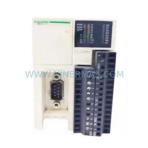
Schneider EOCR-SSD 05 Safety-Reliable Motor Relay for Critical Control
Catalog Continuation
Alternative parts within PLC & Industrial Automation Modules.
Stay inside the same system family when you need substitutes, adjacent modules, or a broader shortlist for procurement review.
SKU: 6SL3224-0BE33-7UA0
Siemens 6SL3224-0BE33-7UA0 Service-Ready Spare Part
SKU: HENF331395R0001 P4LDA
ABB HENF331395R0001 Service-Ready Industrial Spare Part