Original Industrial Spare Part
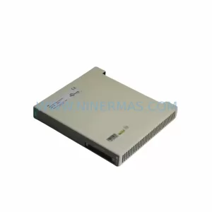
SIEMENS 6SY7000-0AA31 Retrofit-Compatible Rectifier Unit
Verify the part, confirm the platform family, and move straight into quotation with the right commercial details.
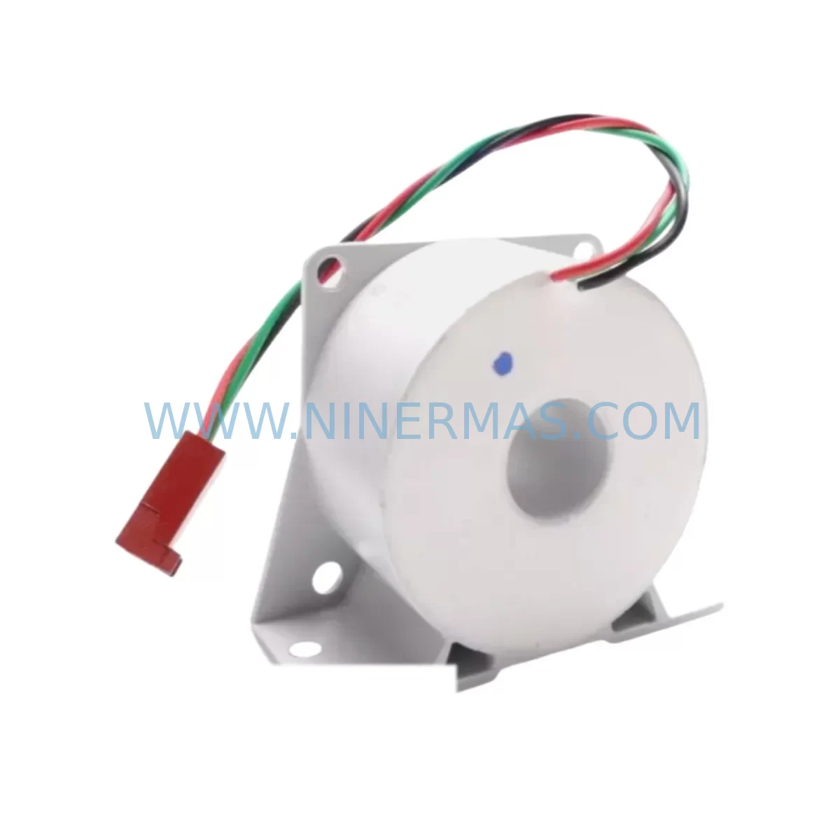
RFQ Ready
- SKU6SY7000-0AA31
- CategoryPLC & Industrial Automation Modules
- BrandSiemens
- SupportAvailability, lead time, condition, and shipping coordination
How Buyers Usually Use This Page
- Confirm the exact part number and platform family before sending the quote request.
- Use direct email when quantity, condition, and destination are already defined internally.
- Switch to the broader brand or category archive when you need alternates nearby.
Series Navigation
Move through the most common platform families behind this part.
Product RFQ
Send this part directly for quotation.
Include quantity, required condition, destination country, and target delivery timing. Current reference: SIEMENS 6SY7000-0AA31 Retrofit-Compatible Rectifier Unit with SKU 6SY7000-0AA31.
SIEMENS 6SY7000-0AA31 Retrofit-Compatible Rectifier Unit for Legacy SIMOVERT MASTERDRIVES Systems
The SIEMENS 6SY7000-0AA31 is a rectifier unit designed for the SIMOVERT MASTERDRIVES series — one of Siemens’ most widely deployed variable frequency drive platforms in heavy industrial environments. As the MASTERDRIVES product line has reached end-of-life status, procurement of original spare parts has become increasingly difficult. NINERMAS maintains verified stock of the 6SY7000-0AA31 to support ongoing plant operations, emergency replacements, and planned retrofit programs across processing, mining, cement, and utilities sectors.
This unit serves as the front-end power conversion stage in MASTERDRIVES MC and VC configurations, converting incoming AC supply into a regulated DC bus voltage for the inverter section. Its compatibility with existing drive cabinets, DC bus bars, and control backplanes makes it a preferred choice for engineers seeking to extend system life without a full drive replacement.
Upgrade Compatibility Table
| Parameter | Details |
|---|---|
| Part Number | 6SY7000-0AA31 |
| Series | SIMOVERT MASTERDRIVES |
| Function | Rectifier / Line-Side Converter Unit |
| Compatible Drive Types | MASTERDRIVES MC, MASTERDRIVES VC |
| Mounting / Installation | Chassis / cabinet-mount; compatible with standard MASTERDRIVES enclosure frames |
| DC Bus Interface | Direct DC bus bar connection; compatible with existing bus bar configurations |
| Communication Compatibility | Compatible with PROFIBUS-DP and USS protocol environments when paired with existing CBP2 or SCI modules |
| Replacement Recommendation | Direct replacement for failed or degraded rectifier stages in MASTERDRIVES installations |
| Commissioning Notes | Verify DC bus pre-charge circuit integrity; confirm line reactor sizing before energisation |
| Warranty | 12 Months from date of shipment |
| Pre-Shipment Testing | Function-tested and inspected prior to dispatch |
| Availability | In stock — ready for immediate shipment |
Retrofit Planning for Existing Automation Systems
Replacing the 6SY7000-0AA31 within an operating MASTERDRIVES installation requires careful coordination across multiple system layers. Before removal of the failed rectifier unit, engineers should document the existing DC bus voltage level, confirm the status of the pre-charge resistor circuit, and verify that the inverter section — typically a companion unit such as the 6SE7031 or 6SE7033 series inverter module — is isolated and de-energised. The DC bus capacitor bank must be fully discharged before any terminal work begins.
On the AC supply side, confirm that the line reactor or input choke — commonly a 4EP3 series reactor in MASTERDRIVES cabinet builds — is rated for the rectifier’s input current. Undersized reactors are a frequent cause of premature rectifier failure in retrofit scenarios. Terminal block wiring should be verified against the original cabinet schematic; in many installations, the L1/L2/L3 input terminals and the DC+ / DC- output terminals are shared with adjacent drive modules on a common DC bus architecture.
For systems using the SIMOVERT MASTERDRIVES compact PLUS format, the backplane connector and slot addressing must be confirmed before the replacement unit is inserted. The CU (Control Unit) — often a 6SE7090-0XX84-0AB0 or similar — retains drive parameters in non-volatile memory, so parameter backup via STARTER or DriveMonitor software is strongly recommended before any hardware swap. If the existing CU is also suspect, a parallel replacement with a known-good control board should be planned as part of the same maintenance window.
Where the installation includes a PROFIBUS-DP network, the CBP2 communication board address settings must be preserved. Incorrect node addressing after a rectifier swap can cause the drive to drop off the PROFIBUS segment, triggering fault responses in the upstream SIMATIC S7-300 or S7-400 PLC. Confirm the DP address DIP switch settings on the CBP2 before re-energisation. Similarly, if the system uses a USS protocol link to an operator panel or HMI — such as an OP7 or TP270 — verify that the baud rate and station address parameters are intact in the CU after the swap.
In multi-drive cabinet configurations, the 6SY7000-0AA31 may supply DC bus power to multiple inverter modules simultaneously. In this topology, the rectifier’s current rating must be confirmed against the aggregate load of all connected inverter stages. If additional I/O expansion has been added to the system since original commissioning — for example, additional ET 200M distributed I/O racks or signal isolators on analogue feedback loops — the total drive load should be recalculated before the replacement rectifier is brought online.
NINERMAS supplies the 6SY7000-0AA31 with a 12-month warranty and full pre-shipment functional testing. Each unit is inspected for DC bus output regulation, gate drive integrity, and thermal management performance before dispatch. Typical lead time from confirmed order to shipment is 1–3 business days for in-stock units.
Downtime Control During System Migration
Minimising unplanned downtime during a MASTERDRIVES rectifier replacement begins with advance preparation. Where production schedules permit, the replacement should be planned during a scheduled maintenance window rather than executed as an emergency repair. Having the 6SY7000-0AA31 on-site as a pre-positioned spare — rather than ordering reactively after a failure — is the single most effective downtime reduction strategy available to maintenance teams managing aging MASTERDRIVES installations.
Before the maintenance window opens, the following preparatory steps should be completed: parameter backup of the CU via STARTER or DriveMonitor, photographic documentation of all terminal wiring, confirmation of DC bus discharge procedure with the site safety team, and verification that the replacement unit’s firmware revision is compatible with the existing CU. In most MASTERDRIVES installations, the rectifier unit itself carries no user-configurable parameters, so the swap is primarily a mechanical and electrical task rather than a software commissioning exercise.
During the swap, the original program logic in the upstream PLC — whether a SIMATIC S7-300, S7-400, or a third-party controller interfacing via PROFIBUS — should remain untouched. The drive’s fault history should be cleared after the replacement unit is installed and before the first test run, to avoid confusion between pre-existing fault codes and any new commissioning faults. A controlled ramp-up at reduced speed setpoint is recommended for the first operational test, allowing the maintenance team to confirm stable DC bus voltage, correct motor rotation direction, and absence of overcurrent or earth fault alarms before returning the drive to full production speed.
For sites where continuous process control is critical, a temporary bypass arrangement using a soft-starter or alternative drive may be considered to maintain partial production throughput during the rectifier replacement window. NINERMAS can advise on compatible interim solutions based on the motor rating and process requirements of the specific installation.
Retrofit Support FAQ
Q: Is the 6SY7000-0AA31 a direct drop-in replacement for the original Siemens unit?
A: Yes. The 6SY7000-0AA31 supplied by NINERMAS is a retrofit-compatible unit verified against the original Siemens specification for the SIMOVERT MASTERDRIVES series. Mechanical dimensions, DC bus terminal positions, and electrical ratings are consistent with the original factory unit. No cabinet modifications are required for a standard replacement.
Q: What pre-shipment testing is performed on each unit?
A: Every 6SY7000-0AA31 dispatched by NINERMAS undergoes functional testing covering DC bus output regulation, gate drive signal integrity, and thermal management performance. A test report is available upon request. All units are covered by a 12-month warranty from the date of shipment.
Q: How do I confirm wiring compatibility before installation?
A: Refer to the original MASTERDRIVES cabinet schematic for terminal designations. The AC input terminals (L1, L2, L3) and DC output terminals (DC+, DC−) on the 6SY7000-0AA31 follow the standard MASTERDRIVES terminal layout. If the original schematic is unavailable, NINERMAS technical support can assist with terminal identification based on the drive frame size and cabinet configuration.
Q: What is the typical lead time and do you hold stock?
A: NINERMAS maintains in-stock inventory of the 6SY7000-0AA31. Standard lead time is 1–3 business days from order confirmation to shipment. For urgent requirements, expedited dispatch is available — contact our sales team directly to confirm current stock levels and shipping options.
| Product Series | SIMOVERT |
|---|---|
| Country of Origin | DE |
Catalog Continuation
More Siemens modules in the catalog.
Use the brand lane to compare nearby part numbers, platform-adjacent modules, and other inquiry-ready listings before sending your final RFQ.
SKU: 6SL3255-0AA00-4HA1
SIEMENS 6SL3255-0AA00-4HA1 Safety-Reliable Terminal Module for Critical Control
SKU: 6AV3617-1JC20-0AX1
Siemens 6AV3617-1JC20-0AX1 Safety-Reliable HMI for Critical Control Sites
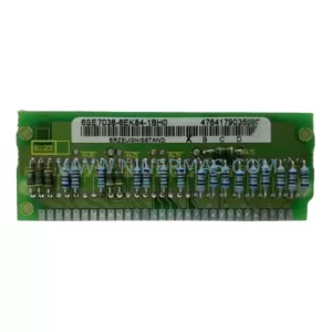
SKU: 6SE7038-6EK84-1BH0
Siemens 6SE7038-6EK84-1BH0 Retrofit Drive Control Module
Catalog Continuation
Alternative parts within PLC & Industrial Automation Modules.
Stay inside the same system family when you need substitutes, adjacent modules, or a broader shortlist for procurement review.
SKU: BM4423-CT1-01600-S01-03-SET
Baumuller BM4423-CT1-01600-S01-03-SET Service-Ready Spare
SKU: TLC4362D312151
Berger Lahr TLC4362D312151 Retrofit-Compatible Servo Drive
SKU: S-D4008-A S-D4008
Reliance S-D4008-A Spare Part for Industrial Maintenance