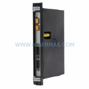
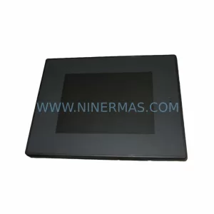
Original Industrial Spare Part
LEC01 Retrofit Pendant for Legacy Systems
Verify the part, confirm the platform family, and move straight into quotation with the right commercial details.
RFQ Ready
- SKULEC01
- CategoryPLC & Industrial Automation Modules
- BrandIndustrial Control Hub
- SupportAvailability, lead time, condition, and shipping coordination
How Buyers Usually Use This Page
- Confirm the exact part number and platform family before sending the quote request.
- Use direct email when quantity, condition, and destination are already defined internally.
- Switch to the broader brand or category archive when you need alternates nearby.
Series Navigation
Move through the most common platform families behind this part.
Product RFQ
Send this part directly for quotation.
Include quantity, required condition, destination country, and target delivery timing. Current reference: LEC01 Retrofit Pendant for Legacy Systems with SKU LEC01.
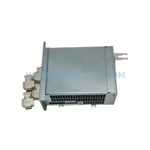
NINERMAS LEC01 Retrofit Pendant for Legacy Systems
The NINERMAS LEC01 is a retrofit-compatible pendant controller engineered for seamless integration into legacy automation environments. Whether you are replacing an end-of-life pendant station on an aging production line, upgrading a discontinued control cabinet assembly, or restoring operational continuity after a critical component failure, the LEC01 delivers a reliable, drop-in compatible solution backed by a 12-month warranty and full pre-shipment functional testing.
Designed specifically for engineers and maintenance teams managing legacy LEC-series control platforms, the LEC01 addresses the most common pain points in retrofit projects: mismatched terminal wiring, incompatible backplane connectors, outdated communication protocols, and constrained installation space inside existing control enclosures. Each unit ships pre-tested against its rated electrical specifications, reducing commissioning time and minimizing unplanned downtime during system changeover.
Upgrade Compatibility Table
| Parameter | LEC01 Specification | Retrofit Notes |
|---|---|---|
| Product Series | LEC Series | Compatible with legacy LEC-series pendant stations |
| Product Type | Pendant Controller | Direct replacement for discontinued pendant assemblies |
| Origin | China (CN) | Manufactured to industrial-grade standards |
| Terminal Wiring | Standard screw-terminal block | Verify existing cable gauge and terminal pitch before installation |
| Communication Compatibility | Hardwired control signal | Confirm signal voltage levels match existing controller I/O card ratings |
| Installation Space | Standard pendant enclosure footprint | Measure existing mounting bracket and cable entry points prior to order |
| Commissioning | Pre-shipment functional test included | On-site loop check and interlock verification recommended |
| Warranty | 12-Month Warranty — covers manufacturing defects under normal operating conditions | |
Retrofit Planning for Existing Automation Systems
Integrating the LEC01 into an existing automation system requires a structured pre-installation review. Before removing the legacy pendant station, maintenance engineers should document the existing wiring diagram, photograph all terminal connections, and record the I/O address assignments used by the host controller — whether that controller is a legacy PLC rack, a distributed I/O node, or a standalone relay logic panel.
In many LEC-series retrofit projects, the pendant controller interfaces directly with a digital input module mounted in the main control rack. If the existing rack uses an older 16-point or 32-point DI card with 24 VDC sourcing logic, confirm that the LEC01 signal outputs are compatible before energizing the circuit. Where the host system uses a power supply module rated at 5 A or 10 A, verify that adding the LEC01 load does not push total draw beyond the supply’s continuous rating — particularly in cabinets that already host multiple analog output modules or communication interface cards.
For systems that have been migrated from proprietary fieldbus protocols to modern Ethernet-based networks, the LEC01 pendant wiring typically terminates at a remote I/O adapter or a terminal block distribution board rather than directly at the main CPU backplane. In these configurations, confirm that the remote I/O adapter’s input scan rate is fast enough to capture the pendant’s momentary pushbutton signals without missed transitions — a common issue when replacing older hardwired interlocks with network-scanned I/O.
Installations involving HMI panels should also account for screen updates: if the legacy HMI graphic displays pendant status via a dedicated bit address, that address mapping must be preserved or remapped in the HMI project file after the LEC01 is commissioned. Similarly, if the control system uses a programming cable or USB-to-serial adapter for on-site PLC program uploads, ensure the updated ladder logic reflecting the new pendant I/O addresses is loaded and verified before returning the line to production.
Where the retrofit involves expanding I/O capacity — for example, adding a signal isolator module between the pendant output and a sensitive analog input card — allow additional wiring time and confirm that the isolator’s input impedance does not load the LEC01 output circuit below its minimum drive threshold. In multi-axis crane or hoist applications, the LEC01 may operate alongside limit switch modules and contactor control relays; interlock logic between these components must be re-verified after any pendant replacement to maintain safe operating sequences.
Downtime Control During System Migration
Minimizing production downtime during a pendant controller replacement requires careful sequencing of the changeover steps. The recommended approach is to complete all pre-installation checks — wiring documentation, I/O address verification, HMI backup, and PLC program export — during a scheduled maintenance window before the physical swap begins. This ensures that if an unexpected wiring discrepancy is discovered during installation, the team can revert to the original pendant without losing the production shift.
During the physical changeover, label every wire before disconnection using the terminal reference numbers from the original wiring diagram. Reconnect the LEC01 terminal by terminal, cross-checking each connection against the documented layout. After wiring is complete, perform a cold-loop check with the main power isolated: use a continuity tester to verify that each pushbutton on the LEC01 closes the correct circuit path to the corresponding I/O terminal on the controller rack.
Once wiring is confirmed, restore control power and perform a live functional test of each pendant button in sequence — jog forward, jog reverse, emergency stop, and any auxiliary functions — while monitoring the PLC I/O status display or HMI diagnostic screen. Confirm that all interlock conditions respond correctly before releasing the equipment for production. The LEC01’s pre-shipment test record, included with each unit, provides a baseline reference for expected electrical behavior during this on-site commissioning phase.
For sites with strict change-management requirements, retain the original pendant station as a spare until the LEC01 has completed a full production cycle without fault. This staged approach protects against latent wiring errors and ensures that the control system can be restored to its previous state within minutes if an issue is detected during initial operation.
Retrofit Support FAQ
Q1: Is the LEC01 a direct drop-in replacement for my existing LEC-series pendant station?
The LEC01 is designed as a retrofit-compatible replacement for legacy LEC-series pendant controllers. In most installations, the mechanical footprint, cable entry configuration, and terminal wiring layout are compatible with the original assembly. However, we recommend verifying the terminal pitch, cable gauge, and signal voltage levels against your existing wiring diagram before installation, as minor variations exist across different production batches of legacy LEC-series equipment.
Q2: What pre-shipment testing is performed on each LEC01 unit?
Every LEC01 unit undergoes a full functional test prior to shipment. This includes verification of each pushbutton circuit’s continuity, confirmation of the emergency stop interlock path, and an electrical insulation check between the control circuit and the enclosure ground. A test record is included with each unit. The LEC01 is covered by a 12-month warranty against manufacturing defects under normal operating conditions.
Q3: Can the LEC01 be used with a modernized PLC rack that uses Ethernet I/O modules instead of the original hardwired backplane?
Yes. The LEC01 outputs standard dry-contact or voltage-level signals that are compatible with most digital input modules, including those used in Ethernet-based remote I/O systems. Confirm the input voltage range and sourcing/sinking configuration of your I/O module before wiring. If your system uses a signal isolator between the pendant and the I/O card, verify that the isolator’s input impedance is compatible with the LEC01’s output drive capability.
Q4: What is the typical lead time and stock availability for the LEC01?
The LEC01 is maintained as a stocked spare parts item to support legacy system maintenance and emergency replacement requirements. Standard lead time for in-stock units is 3–7 business days for international shipments. For large-quantity orders or urgent requirements, contact our sales team directly to confirm current inventory levels and expedited shipping options. All units are dispatched with pre-shipment test documentation and are covered by the 12-month warranty from the date of shipment.
| Product Series | Legacy |
|---|
Catalog Continuation
More Industrial Control Hub modules in the catalog.
Use the brand lane to compare nearby part numbers, platform-adjacent modules, and other inquiry-ready listings before sending your final RFQ.
SKU: 80026-173-23 80026-173-23-R MOX12-P3509B
ICH MOX12-P3509B Safety-Reliable I/O Module for Critical Control
Catalog Continuation
Alternative parts within PLC & Industrial Automation Modules.
Stay inside the same system family when you need substitutes, adjacent modules, or a broader shortlist for procurement review.
SKU: TVB3001-1/STI 3281-000035-19 1D86-006761-41 HPM5F4F4F6S468
TEL TVB3001-1/STI-3281-000035-19 Service-Ready Industrial Spare
SKU: EA-P2M-300-07/15A-0100-01
ETEL EA-P2M-300-07/15A-0100-01 Retrofit Power Module AccurET