Original Industrial Spare Part
ETEL EA-P2M-300-07/15A-0100-01 Retrofit Power Module AccurET
Verify the part, confirm the platform family, and move straight into quotation with the right commercial details.

RFQ Ready
- SKUEA-P2M-300-07/15A-0100-01
- CategoryPLC & Industrial Automation Modules
- BrandETEL
- SupportAvailability, lead time, condition, and shipping coordination
How Buyers Usually Use This Page
- Confirm the exact part number and platform family before sending the quote request.
- Use direct email when quantity, condition, and destination are already defined internally.
- Switch to the broader brand or category archive when you need alternates nearby.
Series Navigation
Move through the most common platform families behind this part.
Product RFQ
Send this part directly for quotation.
Include quantity, required condition, destination country, and target delivery timing. Current reference: ETEL EA-P2M-300-07/15A-0100-01 Retrofit Power Module AccurET with SKU EA-P2M-300-07/15A-0100-01.
ETEL EA-P2M-300-07/15A-0100-01 Retrofit-Compatible Power Module for Legacy AccurET Systems
The ETEL EA-P2M-300-07/15A-0100-01 is a servo drive power module designed for the AccurET motion control platform. With a 300 W continuous output rating and dual current range (7 A / 15 A peak), this module serves as the primary DC bus power supply for AccurET axis drives in multi-axis gantry, direct-drive torque motor, and linear motor applications. As ETEL’s AccurET series reaches end-of-production lifecycle in many configurations, procurement teams and retrofit engineers increasingly rely on verified replacement units to sustain existing production lines without committing to a full platform migration.
This unit is supplied as a tested, retrofit-ready replacement. Each module undergoes pre-shipment functional verification covering DC bus output voltage, current limit response, enable logic, fault relay output, and thermal protection trip. A 12-month warranty is included from the date of shipment, covering manufacturing defects and functional failures under normal operating conditions.
Upgrade Compatibility Table
| Parameter | EA-P2M-300-07/15A-0100-01 | Retrofit Notes |
|---|---|---|
| Continuous Output Power | 300 W | Verify total axis load does not exceed bus capacity when replacing a higher-rated predecessor |
| Continuous / Peak Current | 7 A / 15 A | Match to axis drive current demand; check EA-D series drive datasheets |
| DC Bus Voltage | Nominal per AccurET spec (typically 48–72 VDC) | Confirm bus voltage compatibility with existing EA-D axis modules on the same backplane |
| Backplane Interface | AccurET proprietary backplane connector | Slot position and backplane revision must be confirmed before installation |
| Communication Interface | EtherCAT (AccurET platform) | Firmware version on master controller must support module firmware revision |
| Mounting / Form Factor | AccurET rack-mount module | Confirm rack generation (Gen 1 vs Gen 2 AccurET chassis) for physical fit |
| Cooling | Forced air (internal fan) | Verify cabinet airflow direction matches module exhaust orientation |
| Enable / Fault I/O | Digital I/O via backplane | Map enable signal and fault relay to PLC I/O or safety relay as per original wiring diagram |
| Replacement Scope | Direct module swap within AccurET chassis | No mechanical modification required if chassis generation matches |
| Warranty | 12 Months from shipment | Covers manufacturing defects; pre-shipment test report available on request |
Retrofit Planning for Existing Automation Systems
When integrating the EA-P2M-300-07/15A-0100-01 into an existing AccurET-based motion system, the retrofit scope typically extends beyond the power module itself. Engineers should audit the full drive stack before ordering replacement components. In a standard AccurET multi-axis configuration, the power module shares a backplane with one or more EA-D series axis drive modules, each responsible for a single motor channel. If the original system used an EA-P2M variant with a higher power rating — for example, a 600 W or 1200 W bus supply — the 300 W replacement must be validated against the combined continuous power demand of all connected axis drives.
Terminal wiring at the AC input side should be inspected and re-torqued during any module swap. AccurET power modules accept single-phase or three-phase AC input depending on variant; confirm the input voltage range (100–240 VAC or 200–480 VAC) matches the local supply before energizing. The DC bus output connects internally through the backplane, but external DC bus capacitor banks or regenerative braking resistors — if present in the original installation — must be reconnected and verified for compatibility with the replacement module’s regeneration handling circuit.
On the communication side, AccurET systems rely on EtherCAT as the primary real-time fieldbus. The EA-P2M power module participates in the EtherCAT segment as a network node; its firmware version must be compatible with the EtherCAT master, typically an ETEL DSMAX controller or a third-party EtherCAT master running ETEL’s motion library. Before swapping the module, record the existing node address assignment and confirm that the replacement unit’s factory firmware revision is supported by the master’s configuration file. If the system uses an older DSMAX generation, a firmware update on the master may be required before the new power module is recognized correctly on the EtherCAT ring.
I/O mapping is another critical checkpoint. The enable signal, drive-ready output, and fault relay — routed through the AccurET backplane — must be traced back to the safety relay module or PLC safety I/O card in the control cabinet. In installations where a Pilz PNOZ or similar safety relay monitors the drive-ready chain, the relay logic must be verified after module replacement to ensure the safety circuit closes correctly before motion is permitted. Similarly, if the cabinet includes a Beckhoff EK1100 EtherCAT coupler or similar I/O expansion for auxiliary signals, the node topology should be re-validated after the power module is replaced and the EtherCAT segment is re-initialized.
For systems that also include ETEL linear motor stages or torque motor rotary tables, the motor feedback interface — typically EnDat 2.2 or HIPERFACE — is handled at the axis drive level (EA-D modules), not the power module. However, the power module’s bus stability directly affects encoder supply voltage ripple, so a degraded or aging power module can manifest as intermittent encoder errors before a hard fault occurs. Replacing the EA-P2M-300-07/15A-0100-01 in such cases often resolves encoder communication faults that were previously misattributed to the feedback cable or the encoder head itself.
Where the original installation includes an ETEL HMI panel or a third-party operator interface running ETEL’s visualization layer, no HMI screen modifications are required for a like-for-like power module replacement. However, if the retrofit involves upgrading from an older AccurET chassis generation to a current-production backplane, the HMI tag mapping for drive status bits should be reviewed, as register addresses may differ between chassis revisions.
Downtime Control During System Migration
Minimizing unplanned downtime is the primary concern in any AccurET power module replacement. The recommended approach is to pre-stage the replacement EA-P2M-300-07/15A-0100-01 unit in the workshop, verify its pre-shipment test report, and prepare a module swap checklist before the maintenance window begins. The swap itself — assuming the chassis generation matches and no firmware update is required — can typically be completed within a two-to-four hour window, including re-torquing AC input terminals, re-seating the module on the backplane, cycling power, and confirming EtherCAT node recognition on the master.
Before powering down the system, export the current motion program from the DSMAX controller or the engineering workstation running ETEL’s MotionSoft or equivalent configuration tool. Store the program backup on an isolated drive. This protects the axis tuning parameters, cam profiles, and safety limit configurations that would otherwise need to be re-entered manually if the controller loses its non-volatile memory during the power cycle.
During the power-down sequence, discharge the DC bus capacitors fully before handling the power module. AccurET systems typically include a bus discharge indicator LED on the power module faceplate; do not remove the module until the LED extinguishes. After installing the replacement unit, perform a controlled power-up with all axis drives in the disabled state. Confirm DC bus voltage is within specification before enabling individual axes one at a time. This staged enable sequence isolates any axis-level fault from the power module and prevents a cascading fault condition that could trip the main circuit breaker and extend the downtime window.
If the system includes a regenerative power supply or a shared DC bus architecture with multiple AccurET chassis, coordinate the replacement sequence with the broader bus topology. Isolate the affected chassis segment from the shared bus before removing the power module to prevent back-feeding from adjacent chassis during the swap.
Retrofit Support FAQ
Q: Is the EA-P2M-300-07/15A-0100-01 a direct drop-in replacement for other EA-P2M variants with different power ratings?
A: The physical backplane connector and mounting format are shared across the AccurET EA-P2M family, but the power rating must match or exceed the combined continuous load of the connected axis drives. A 300 W unit cannot substitute for a 600 W or 1200 W variant without first verifying that the total axis power demand falls within the 300 W continuous limit. Always calculate the worst-case simultaneous axis load before confirming the replacement rating.
Q: What pre-shipment testing is performed on replacement units?
A: Each EA-P2M-300-07/15A-0100-01 supplied by NINERMAS undergoes functional verification covering DC bus output voltage accuracy, current limit response at 7 A continuous and 15 A peak, enable logic sequencing, fault relay output continuity, and thermal protection trip point. A test report is available on request. The 12-month warranty covers manufacturing defects and functional failures under normal operating conditions from the date of shipment.
Q: How do I confirm firmware compatibility before installing the replacement module?
A: Record the firmware revision displayed on the existing power module’s faceplate label or read it via the ETEL configuration tool before removal. Compare this revision against the replacement unit’s firmware label. If the revisions differ, consult the ETEL firmware compatibility matrix for your DSMAX controller version. In most cases, the replacement unit’s firmware is backward-compatible, but a master firmware update may be required for older DSMAX generations. Contact our technical team with your controller serial number and existing firmware revision for a pre-installation compatibility check.
Q: What is the typical lead time and stock availability?
A: NINERMAS maintains stock of the EA-P2M-300-07/15A-0100-01 to support urgent retrofit and breakdown replacement requirements. Standard lead time for in-stock units is 3–7 business days for international shipment. For time-critical breakdowns, expedited shipping options are available. Contact our sales team at sale@ninermas.com or +0086 187 5021 5667 to confirm current stock status and delivery schedule before placing your order.
| Product Series | Other series |
|---|
Catalog Continuation
More ETEL modules in the catalog.
Use the brand lane to compare nearby part numbers, platform-adjacent modules, and other inquiry-ready listings before sending your final RFQ.
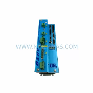
SKU: DSB2S154-211E-000H
ETEL DSB2S154-211E-000H Spare Part for Industrial Maintenance
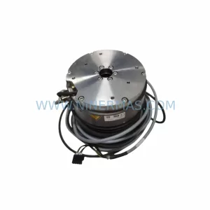
SKU: SME-RTMB01401003RBS0000
ETEL SME-RTMB01401003RBS0000 Retrofit-Compatible Motion Module
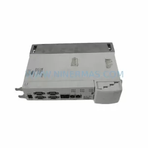
SKU: D3-DA 330/A-0311-20
ETEL D3-DA 330/A-0311-20 Safety-Reliable Drive for Critical Sites
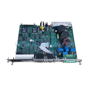
SKU: DSC2P142-111-000
Etel DSC2P142-111-000 Retrofit-Compatible Digital Servo Amplifier
Catalog Continuation
Alternative parts within PLC & Industrial Automation Modules.
Stay inside the same system family when you need substitutes, adjacent modules, or a broader shortlist for procurement review.
SKU: TVB3001-1/STI 3281-000035-19 1D86-006761-41 HPM5F4F4F6S468
TEL TVB3001-1/STI-3281-000035-19 Service-Ready Industrial Spare
SKU: 6SE7035-1EJ84-1BH0
Siemens 6SE7035-1EJ84-1BH0 Retrofit ABO Module Legacy VFD