Original Industrial Spare Part
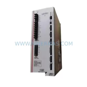
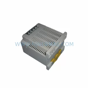
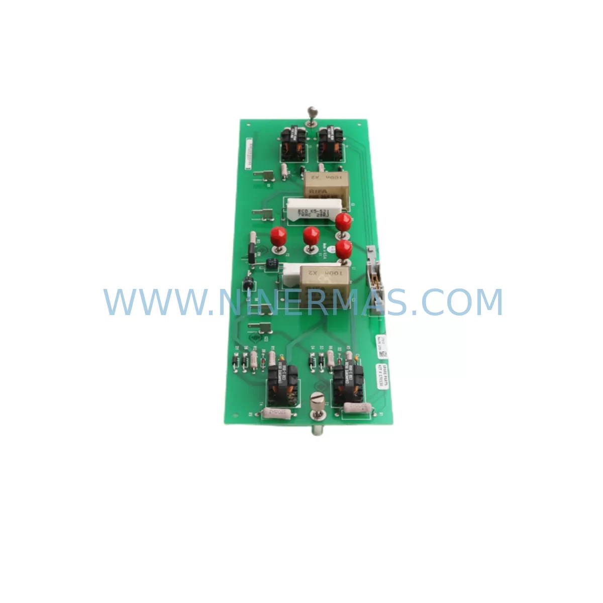
Allen-Bradley SP-170025 Retrofit-Compatible Power Supply for Legacy Systems
Verify the part, confirm the platform family, and move straight into quotation with the right commercial details.
RFQ Ready
- SKUSP-170025 SP-170130 170026-01
- CategoryPLC & Industrial Automation Modules
- BrandAllen-Bradley
- SupportAvailability, lead time, condition, and shipping coordination
How Buyers Usually Use This Page
- Confirm the exact part number and platform family before sending the quote request.
- Use direct email when quantity, condition, and destination are already defined internally.
- Switch to the broader brand or category archive when you need alternates nearby.
Series Navigation
Move through the most common platform families behind this part.
Product RFQ
Send this part directly for quotation.
Include quantity, required condition, destination country, and target delivery timing. Current reference: Allen-Bradley SP-170025 Retrofit-Compatible Power Supply for Legacy Systems with SKU SP-170025 SP-170130 170026-01.
Allen-Bradley SP-170025 Retrofit-Compatible Power Supply for Legacy Systems
The Allen-Bradley SP-170025 (cross-referenced as SP-170130 and 170026-01) is a power supply module originally designed for the SLC 500 and PLC-5 control platforms — two of the most widely deployed programmable logic controller families in industrial automation history. As these platforms approach or have passed their end-of-life milestones, facilities engineers and maintenance teams face the critical challenge of sourcing reliable replacement components that can sustain production continuity without triggering a full system overhaul.
NINERMAS maintains verified inventory of the SP-170025, SP-170130, and 170026-01 power supply modules, fully tested prior to shipment and backed by a 12-month warranty. Whether you are managing a planned retrofit, responding to an unplanned failure, or building a strategic spare parts buffer, this module provides a direct, drop-in replacement path for your existing SLC or PLC-5 rack infrastructure.
Upgrade Compatibility Table
| Parameter | SP-170025 / SP-170130 / 170026-01 | Retrofit Notes |
|---|---|---|
| Compatible Platform | SLC 500, PLC-5 Series | Verify rack slot assignment before installation |
| Mounting / Form Factor | SLC 500 modular rack (1746 chassis) | Confirm chassis model: 1746-A4, 1746-A7, 1746-A10, 1746-A13 |
| Input Voltage | 85–264 VAC / 47–63 Hz | Match site supply voltage; check panel transformer if applicable |
| Output / Load Capacity | Refer to original nameplate rating | Calculate total I/O module current draw before replacement |
| Communication Compatibility | DH+, DH-485, RS-232 (platform-dependent) | No protocol change required for like-for-like swap |
| Backplane Interface | SLC 500 standard backplane connector | Inspect backplane pins for corrosion or damage prior to seating |
| Replacement Type | Direct drop-in replacement | No program modification required for power supply swap |
| Commissioning Requirement | Power-cycle and fault-clear after installation | Verify all I/O modules re-initialize correctly post-swap |
| Warranty | 12 Months | Covered from date of shipment; includes functional test certificate |
Retrofit Planning for Existing Automation Systems
When the SP-170025 power supply fails or is flagged for proactive replacement during a scheduled maintenance window, the scope of work extends well beyond simply swapping the module. A successful retrofit requires a structured review of the entire control cabinet environment.
Begin with a power budget audit. The SLC 500 chassis — whether a 4-slot 1746-A4, a 7-slot 1746-A7, or a larger 1746-A13 — distributes backplane power across all installed modules. Before installing the replacement SP-170025 or SP-170130, calculate the combined current draw of all installed I/O modules, including 1746-IB16 digital input modules, 1746-OB16 digital output modules, and any analog modules such as the 1746-NI4 or 1746-NO4I. Exceeding the power supply’s rated output will cause intermittent faults or premature failure of the new unit.
Next, inspect the terminal wiring and field device connections. In aging SLC installations, terminal blocks often show signs of oxidation, loose crimps, or insulation degradation. This is the ideal moment to re-torque all terminal screws, replace any suspect ferrules, and verify that field wiring labels match the current I/O map in the processor program. If the system uses a 1747-L532 or 1747-L541 SLC 5/03 or 5/04 processor, confirm that the processor firmware revision is compatible with the current RSLogix 500 project file before powering up.
For facilities that are simultaneously upgrading their communication infrastructure, the power supply replacement window is a practical opportunity to evaluate the existing DH-485 or DH+ network topology. If the site is migrating toward EtherNet/IP, consider whether a 1761-NET-ENI serial-to-Ethernet adapter or a 1747-AENTR EtherNet/IP adapter module should be added to the rack during the same outage. This avoids a second planned shutdown later in the project.
HMI continuity is another critical consideration. Many SLC-based lines are monitored by PanelView 550 or PanelView 600 terminals communicating over DH-485. After the power supply is replaced and the processor restarts, verify that the HMI re-establishes its communication link and that all screen tags are reading correctly. If the HMI application references node addresses that have shifted due to rack reconfiguration, update the node assignment in PanelView Builder or FactoryTalk View ME before returning the line to production.
Where the retrofit scope includes I/O expansion — for example, adding a remote I/O drop via a 1747-ASB adapter or integrating a new 1746-HSCE2 high-speed counter module — confirm that the expanded I/O map does not conflict with existing file addresses in the SLC processor program. Use RSLogix 500 offline to simulate the new configuration before going live. If the project involves migrating from SLC to a CompactLogix 5370 or CompactLogix 5380 platform, the SP-170025 replacement can serve as a bridge solution that keeps the legacy line running while the migration project is completed in parallel on a test bench.
Finally, for systems that include signal isolators or intrinsic safety barriers between field instruments and SLC analog input modules, verify that the isolator power rails are fed from a separate 24 VDC supply and are not dependent on the SLC backplane power. This is a common oversight that causes analog signal errors after a power supply replacement.
Downtime Control During System Migration
Unplanned downtime is the highest-cost risk in any legacy system retrofit. When the SP-170025 or 170026-01 power supply is the cause of a line stoppage, the priority is to restore production as quickly as possible while protecting the integrity of the existing control program and field wiring.
Pre-staged replacement units are the single most effective downtime reduction strategy. NINERMAS maintains ready-to-ship inventory of the SP-170025, SP-170130, and 170026-01 modules, allowing facilities teams to receive a tested replacement unit within days rather than weeks. Each unit ships with a functional test certificate confirming output voltage stability and backplane interface integrity.
Before removing the failed power supply, back up the SLC processor program using RSLogix 500 or a 1747-PIC programming cable connected to the processor’s DH-485 port. Save the .RSS project file to a secure location. This step takes less than five minutes and eliminates the risk of program loss if the processor loses its battery backup during the power interruption.
During the physical swap, do not disturb the I/O module wiring. The power supply occupies the leftmost slot of the SLC 500 chassis and can be removed and replaced without touching any field wiring terminals. After seating the new module, restore AC power and observe the processor status indicators. A healthy SLC processor will cycle through its startup diagnostics and return to RUN mode within seconds if the program is intact and all I/O modules are responding normally.
For sites with redundant control architectures — for example, dual SLC racks with a 1747-BSN backup scanner — the power supply replacement can often be performed on the standby rack while the primary rack maintains production control, reducing effective downtime to near zero. After the replacement is validated on the standby rack, a controlled switchover transfers control before the primary rack is serviced.
Document the replacement in the site’s maintenance log, including the module serial number, installation date, and the name of the technician who performed the work. This record supports warranty claims and provides traceability for future audits.
Retrofit Support FAQ
Q1: Is the SP-170025 a direct replacement for the SP-170130 and 170026-01?
Yes. The SP-170025, SP-170130, and 170026-01 are cross-referenced part numbers for the same power supply module used in the Allen-Bradley SLC 500 and PLC-5 control platforms. All three references are interchangeable in the same chassis slot. NINERMAS verifies cross-reference compatibility prior to shipment.
Q2: Will I need to modify my SLC program after replacing the power supply?
No. The SP-170025 is a like-for-like hardware replacement. The SLC processor program, I/O configuration, and communication settings are stored in the processor module — not in the power supply. After the replacement, the processor will resume normal operation using the existing program. No RSLogix 500 edits are required for a standard power supply swap.
Q3: How do I verify the replacement unit before installing it in my production rack?
NINERMAS ships each SP-170025, SP-170130, and 170026-01 unit with a functional test certificate. For additional on-site verification, you can bench-test the module by connecting it to a known-good SLC 500 chassis with a minimal I/O load (one or two 1746-IB16 input modules) and confirming that the backplane power indicators are stable before installing it in the production rack.
Q4: What does the 12-month warranty cover?
The 12-month warranty covers manufacturing defects and functional failures under normal operating conditions from the date of shipment. It includes free replacement or repair of the module. The warranty does not cover damage caused by incorrect installation, overvoltage events, or physical mishandling. Contact sale@ninermas.com with your order number and a description of the fault to initiate a warranty claim.
| Product Series | PLC-5 |
|---|---|
| Country of Origin | US |
Catalog Continuation
More Allen-Bradley modules in the catalog.
Use the brand lane to compare nearby part numbers, platform-adjacent modules, and other inquiry-ready listings before sending your final RFQ.
Catalog Continuation
Alternative parts within PLC & Industrial Automation Modules.
Stay inside the same system family when you need substitutes, adjacent modules, or a broader shortlist for procurement review.
SKU: PCE-2 LIF-1 K15MB000 671-5532-02
Tektronix PCE-2 LIF-1 K15MB000 671-5532-02 Service-Ready Spare Part