Original Industrial Spare Part
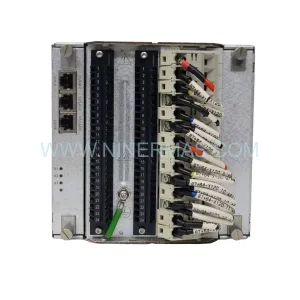
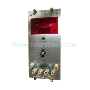
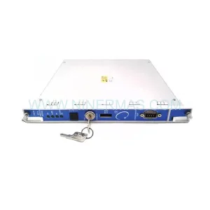
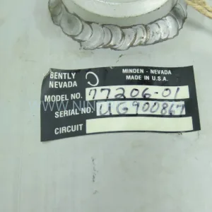
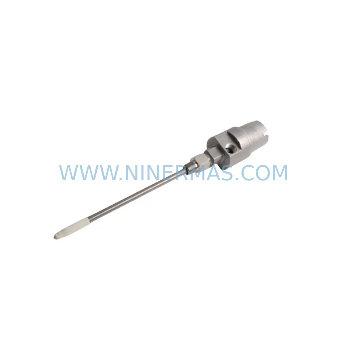
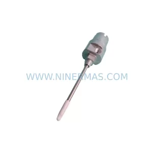
Bently Nevada 21000-16-10-00-053-03-02 Retrofit Proximity Probe
Verify the part, confirm the platform family, and move straight into quotation with the right commercial details.
RFQ Ready
- SKU21000-16-10-00-053-03-02
- CategoryTSI & Rotating Machinery Monitoring
- BrandBently Nevada
- SupportAvailability, lead time, condition, and shipping coordination
How Buyers Usually Use This Page
- Confirm the exact part number and platform family before sending the quote request.
- Use direct email when quantity, condition, and destination are already defined internally.
- Switch to the broader brand or category archive when you need alternates nearby.
Series Navigation
Move through the most common platform families behind this part.
Product RFQ
Send this part directly for quotation.
Include quantity, required condition, destination country, and target delivery timing. Current reference: Bently Nevada 21000-16-10-00-053-03-02 Retrofit Proximity Probe with SKU 21000-16-10-00-053-03-02.
Bently Nevada 21000-16-10-00-053-03-02 Retrofit-Compatible Proximity Probe Housing for Legacy Systems
The Bently Nevada 21000-16-10-00-053-03-02 is a ruggedized proximity probe housing engineered for demanding industrial environments where vibration monitoring is critical to machine health and operational continuity. As legacy Bently Nevada 3300 Series and 7200 Series monitoring systems reach end-of-life, plant engineers and reliability teams increasingly rely on this component to maintain measurement integrity during phased retrofits, control cabinet upgrades, and full system migrations to modern platforms such as the Bently Nevada 3500 Series machinery protection system.
This probe housing is designed to interface directly with standard Bently Nevada extension cables and proximitor sensors, preserving the existing signal chain without requiring full rewiring of the field junction box. When replacing discontinued probe assemblies in rotating machinery applications — including steam turbines, gas compressors, centrifugal pumps, and gearboxes — engineers must verify the probe gap voltage, target material compatibility, and the linear range of the installed proximitor before commissioning. The 21000-16-10-00-053-03-02 housing accommodates standard 8 mm probe tip geometry and is compatible with the Bently Nevada 330100 and 330130 proximity probe families, simplifying cross-referencing during spare parts lifecycle planning.
Upgrade Compatibility Table
| Parameter | Legacy Reference | 21000-16-10-00-053-03-02 Specification | Retrofit Notes |
|---|---|---|---|
| Probe Tip Diameter | 8 mm standard | 8 mm | Direct fit; no adapter required |
| Housing Material | Stainless steel | Ruggedized stainless steel | Suitable for high-vibration, high-temperature zones |
| Cable Interface | Standard Bently Nevada extension cable | Compatible with 330130-045-00-00 extension cable | Verify cable length before installation |
| Proximitor Compatibility | 3300 XL / 7200 Series proximitor | Compatible with 3300 XL proximitor (330180) | Confirm gap voltage at 1.0 mm: −10 VDC nominal |
| Mounting Thread | M10 × 1.0 or 3/8-24 UNF | Confirm per installation drawing | Check existing bracket thread before ordering |
| Communication / Signal | Analog −24 VDC bias | Analog −24 VDC bias | No protocol migration required |
| Installation Space | Standard probe bracket clearance | Same envelope as legacy housing | Verify radial clearance in bearing housing |
| Replacement Recommendation | Discontinued 21000 Series housings | Direct OEM-equivalent replacement | No firmware or rack configuration change needed |
| Commissioning Focus | Gap setting, polarity, signal noise | Set gap to −10 VDC ± 0.5 VDC at nominal position | Use Bently Nevada gap tool or calibrated feeler gauge |
| Warranty | — | 12-Month Warranty | Covered from date of shipment |
Retrofit Planning for Existing Automation Systems
Successful integration of the 21000-16-10-00-053-03-02 into an existing machinery protection architecture requires a structured approach that accounts for both mechanical and electrical compatibility across the full signal path. In a typical Bently Nevada 3500 Series rack-based system, the probe signal travels from the field-mounted housing through a Bently Nevada 330130 extension cable to a 3300 XL proximitor (model 330180), which conditions the signal before it reaches the 3500/40M proximitor I/O module in the 3500 rack. Each element in this chain must be verified before the replacement probe housing is installed.
When the existing system uses an older 7200 Series monitor rack, the migration path typically involves replacing the 7200 Series monitor cards with 3500/40M or 3500/42M I/O modules and updating the rack configuration in System 1 Evolution software. During this process, the 21000-16-10-00-053-03-02 housing can remain in the field while the rack-side electronics are upgraded, minimizing the scope of mechanical work at the machine. Engineers should document the existing channel assignments, alert and danger setpoints, and OK relay logic from the 7200 Series configuration before decommissioning the old rack.
Power supply integrity is a critical checkpoint. The 3500 rack relies on a dedicated −24 VDC bias supply routed through the proximitor to the probe. If the existing power distribution uses a legacy Bently Nevada power supply module (such as the 3500/15 or 3500/05), verify that the supply capacity is sufficient to support all active probe channels simultaneously, particularly when adding new I/O modules during an expansion. A shortfall in bias supply current is a common cause of intermittent OK relay dropout during commissioning.
Terminal wiring at the I/O module must be confirmed against the 3500/40M wiring diagram. The probe common, probe signal, and shield connections must be landed correctly to avoid ground loops that introduce noise into the vibration signal. When the field cable run exceeds 30 metres, engineers should also verify that the cable capacitance remains within the proximitor’s specified linear range. In installations where the Bently Nevada 3500/22M transient data interface module is present, confirm that the probe channel is mapped correctly in the TDI configuration to ensure that waveform data is captured alongside the overall vibration level.
For plants operating Emerson DeltaV or Honeywell Experion PKS as the supervisory control layer, the 3500 rack communicates via Modbus TCP or OPC DA/UA through a dedicated communications gateway. No changes to the DCS tag database are required when replacing only the probe housing, as the rack-level channel address and engineering unit scaling remain unchanged. However, if the retrofit includes replacing a 7200 Series monitor with a 3500 Series rack, the DCS engineer must update the Modbus register map and verify that all alarm annunciation paths — including the 3500/92 communication gateway module — are functioning correctly before returning the machine to service.
Downtime Control During System Migration
Minimising planned outage duration during a probe housing replacement or broader machinery protection system upgrade requires careful pre-staging and a clear sequence of work. Before the machine is taken offline, the replacement 21000-16-10-00-053-03-02 housing should be bench-tested with a calibrated proximitor and a target material representative of the actual shaft material to confirm the gap voltage curve and linear range. This pre-commissioning step eliminates the most common cause of extended outages: discovering a gap or signal issue only after the machine is shut down and the probe is installed.
The original program logic in the 3500 rack — including setpoint values, time delays, OK relay configuration, and channel inhibit states — should be exported from System 1 Evolution and archived before any hardware changes are made. This backup allows the commissioning team to restore the exact pre-retrofit configuration if an unexpected issue arises during the outage window. If the retrofit also involves replacing the 3500/20 rack power supply or adding a 3500/32 four-channel relay module for expanded trip logic, these changes should be staged and tested on a spare rack in the workshop before the planned outage begins.
During the outage, the recommended sequence is: isolate the machine, inhibit the affected channels in the 3500 rack to prevent spurious trips during probe removal, replace the housing, set the probe gap, restore channel inhibit states, verify the OK relay status, and confirm the vibration reading against a reference measurement before releasing the machine for restart. This sequence typically allows a single-probe replacement to be completed within a two-hour maintenance window, even in confined bearing housing locations where access is restricted.
For multi-machine retrofits across a production line, a rolling replacement strategy — where one machine is taken offline while others continue to operate — is strongly recommended to maintain overall plant throughput. Coordinating the probe replacement schedule with the control room operator ensures that the DCS alarm management system is updated to reflect the inhibited channels, preventing nuisance alarms from reaching the operations team during the work window.
Retrofit Support FAQ
Q1: Is the 21000-16-10-00-053-03-02 a direct replacement for discontinued Bently Nevada 21000 Series probe housings?
Yes. The 21000-16-10-00-053-03-02 is an OEM-equivalent replacement for discontinued housings within the Bently Nevada 21000 Series. It maintains the same mechanical envelope, thread specification, and signal interface, allowing direct substitution without modification to the existing probe bracket or extension cable. Customers should confirm the mounting thread and cable connector type against their installation drawing before ordering.
Q2: What commissioning checks are required after installing the replacement housing?
After installation, set the probe gap to achieve a proximitor output of −10 VDC ± 0.5 VDC at the nominal shaft position using a calibrated gap tool or feeler gauge. Verify the OK relay status in the 3500 rack, confirm the vibration reading is within the expected baseline range, and check for signal noise on the waveform display in System 1 Evolution. If the system includes a 3500/22M transient data interface, confirm that the channel is active and recording correctly.
Q3: Does replacing the probe housing require any changes to the 3500 rack configuration or DCS tag database?
No. A like-for-like housing replacement does not require changes to the 3500 rack configuration, Modbus register map, or DCS tag database. The channel address, engineering unit scaling, and setpoint values remain unchanged. Configuration changes are only required if the retrofit also involves replacing the monitor card, adding new I/O modules, or migrating from a 7200 Series rack to a 3500 Series rack.
Q4: What are the warranty terms and how is stock availability confirmed?
All units are covered by a 12-month warranty from the date of shipment, covering manufacturing defects and functional failures under normal operating conditions. Each unit undergoes functional testing prior to dispatch. Stock availability is confirmed at the time of order; customers with urgent requirements are encouraged to contact the sales team directly to verify lead time and arrange priority shipment.
| Product Series | 21000 Series |
|---|---|
| Country of Origin | US |
Catalog Continuation
More Bently Nevada modules in the catalog.
Use the brand lane to compare nearby part numbers, platform-adjacent modules, and other inquiry-ready listings before sending your final RFQ.
SKU: 330103-00-10-10-11-05
Bently Nevada 330103-00-10-10-11-05 Safety Proximity Transducer
SKU: 330703-000-060-90-02-00
Bently Nevada 330703-000-060-90-02-00 Retrofit Module
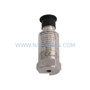
SKU: 177230-00-01-CN 16925-33
Bently Nevada 177230-00-01-CN 16925-33 Service-Ready Spare Part for Industrial Maintenance
Catalog Continuation
Alternative parts within TSI & Rotating Machinery Monitoring.
Stay inside the same system family when you need substitutes, adjacent modules, or a broader shortlist for procurement review.
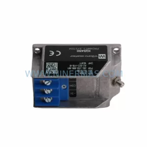
SKU: 204-900-000-011
Vibro-meter 204-900-000-011 Safety-Reliable Vibration Monitor
SKU: 330904-00-09-10-02-05/CN
Bently Nevada 330904-00-09-10-02-05/CN Safety-Reliable Vibration Monitor
SKU: 21000-28-05-15-024-03-02
Bently Nevada 21000-28-05-15-024-03-02 Retrofit Proximity Probe