Original Industrial Spare Part
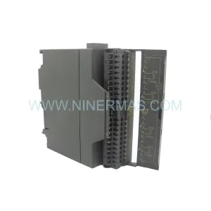
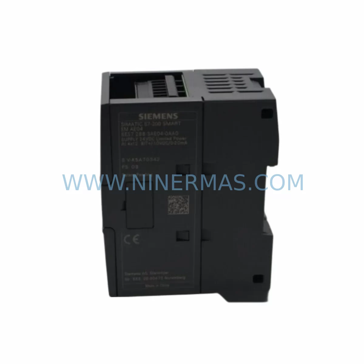
SIEMENS 6ES7288-3AQ02-0AA0 Retrofit-Compatible Analog Output Module
Verify the part, confirm the platform family, and move straight into quotation with the right commercial details.
RFQ Ready
- SKU6ES7288-3AQ02-0AA0
- CategoryPLC & Industrial Automation Modules
- BrandSiemens
- SupportAvailability, lead time, condition, and shipping coordination
How Buyers Usually Use This Page
- Confirm the exact part number and platform family before sending the quote request.
- Use direct email when quantity, condition, and destination are already defined internally.
- Switch to the broader brand or category archive when you need alternates nearby.
Series Navigation
Move through the most common platform families behind this part.
Product RFQ
Send this part directly for quotation.
Include quantity, required condition, destination country, and target delivery timing. Current reference: SIEMENS 6ES7288-3AQ02-0AA0 Retrofit-Compatible Analog Output Module with SKU 6ES7288-3AQ02-0AA0.
SIEMENS 6ES7288-3AQ02-0AA0 Retrofit-Compatible Analog Output Module for Legacy System Modernization
The SIEMENS 6ES7288-3AQ02-0AA0 is a 2-channel analog output expansion module designed for the S7-200 SMART series PLC platform. As industrial facilities face increasing pressure to extend the operational life of aging automation infrastructure, this module has become a critical component in retrofit projects targeting legacy S7-200 and early S7-200 SMART installations. Whether you are replacing a failed unit on an active production line, upgrading a control cabinet to meet new process requirements, or migrating from an obsolete analog output card, the 6ES7288-3AQ02-0AA0 provides a reliable, drop-in compatible solution that minimizes engineering rework and reduces total downtime exposure.
Each module delivers two independently configurable analog output channels supporting both voltage (0–10 V) and current (0–20 mA / 4–20 mA) signal ranges, making it suitable for driving proportional valves, variable frequency drives, positioners, and other field devices commonly found in process control, HVAC, water treatment, and light manufacturing environments. The module connects directly to the S7-200 SMART CPU via the integrated expansion bus, eliminating the need for additional communication wiring between the CPU and the output stage.
Upgrade Compatibility Table
| Parameter | 6ES7288-3AQ02-0AA0 | Legacy / Predecessor Units |
|---|---|---|
| Output Channels | 2 analog output channels | Typically 2 channels (varies by model) |
| Signal Range | 0–10 V / 0–20 mA / 4–20 mA | 0–10 V / 4–20 mA (model dependent) |
| Resolution | 12-bit | 11-bit or 12-bit (model dependent) |
| Bus Interface | S7-200 SMART expansion bus | S7-200 SMART expansion bus |
| Installation | DIN rail, side-by-side with CPU | DIN rail, same form factor |
| Terminal Wiring | Removable screw terminal block | Removable screw terminal block |
| Communication Compatibility | STEP 7-Micro/WIN SMART | STEP 7-Micro/WIN SMART |
| Replacement Recommendation | Direct replacement for AQ02 variants | Verify address offset in program |
| Commissioning Notes | Confirm AQW address mapping in CPU | Re-download program after swap |
| Warranty | 12 Months | N/A (end-of-life / discontinued) |
Retrofit Planning for Existing Automation Systems
Successful integration of the 6ES7288-3AQ02-0AA0 into an existing control system begins well before the module arrives on site. Engineers should start by auditing the current expansion module configuration on the S7-200 SMART CPU — typically a CPU SR20, CPU ST30, CPU SR40, or CPU ST60 — to confirm the total number of expansion slots in use and the available power budget on the 5 V DC expansion bus. The CPU’s internal power supply imposes a combined current limit across all connected expansion modules, and adding or replacing an analog output module requires verifying that the new module’s 5 V consumption does not push the system over its rated capacity.
Terminal wiring is the next critical checkpoint. The 6ES7288-3AQ02-0AA0 uses a removable screw terminal block, which simplifies field replacement when the original wiring labels are intact. Before disconnecting the legacy module, photograph or document all field wiring connections, noting the signal type (voltage or current) and the corresponding field device for each channel. If the existing installation uses shielded twisted-pair cable for analog signal runs — as is standard practice for noise immunity in environments with variable frequency drives such as the Siemens SINAMICS G120 or MICROMASTER 440 — confirm that cable shields are grounded at one end only to avoid ground loops that can introduce offset errors in the output signal.
On the software side, open the project in STEP 7-Micro/WIN SMART and locate the analog output instructions referencing the AQW (Analog Output Word) addresses assigned to the module being replaced. The S7-200 SMART platform assigns AQW addresses sequentially based on the physical slot position of each expansion module. If the 6ES7288-3AQ02-0AA0 is installed in the same slot as the module it replaces, the AQW address mapping will remain unchanged and no program modification is required. However, if the slot position changes — for example, because a failed module is being replaced with a unit installed in a different position due to physical damage to the backplane connector — the AQW addresses must be updated in the program and the project must be re-downloaded to the CPU.
For systems that also include digital I/O expansion modules such as the 6ES7288-2DE08-0AA0 (8DI/8DO relay) or the 6ES7288-2DR08-0AA0, confirm that the digital module addresses (IB and QB byte assignments) are not affected by the analog module swap. Mixed expansion configurations are common in control cabinets where the S7-200 SMART CPU manages both discrete and analog field devices simultaneously, and address conflicts between module types can cause unexpected output behavior during commissioning.
If the retrofit scope extends beyond a single module replacement to include a broader control cabinet upgrade — for example, migrating from an older S7-200 CPU 224 or CPU 226 to the S7-200 SMART platform — additional planning is required for HMI screen updates. Existing SIMATIC HMI panels or third-party touch screens connected via RS-485 Modbus RTU or PPI protocol will need their tag databases updated to reflect any changes in data register addresses resulting from the platform migration. The S7-200 SMART supports Modbus RTU master and slave communication natively, which simplifies protocol migration from legacy PPI-only installations.
In applications where the analog output module drives a proportional control valve or a pneumatic positioner, verify the output signal range configuration in both the hardware configuration tool and the field device itself. A mismatch between the module’s configured output range and the field device’s input range — for example, a module configured for 0–10 V driving a positioner calibrated for 4–20 mA — will result in incorrect actuator positioning and may trigger process alarms. This verification step is particularly important when replacing modules sourced from different production batches or when the original configuration documentation is incomplete.
Downtime Control During System Migration
Minimizing production downtime during an analog output module replacement requires a structured approach that begins with pre-staging the replacement unit and completing all software preparation before the maintenance window opens. Download a backup copy of the current CPU program using STEP 7-Micro/WIN SMART and store it on a local engineering workstation as well as a USB drive kept with the replacement module. This ensures that if the CPU memory is inadvertently cleared during the swap — which can occur if the CPU loses power while the expansion bus connector is being reseated — the program can be restored immediately without waiting for remote access to a file server.
During the physical swap, power down the entire S7-200 SMART system by removing the 24 V DC supply to the CPU. Do not attempt a hot-swap of expansion modules on the S7-200 SMART platform, as the expansion bus does not support live insertion and doing so risks damaging the bus connector on both the CPU and the module. Once the replacement 6ES7288-3AQ02-0AA0 is seated and the terminal block is reconnected, restore power and allow the CPU to complete its startup diagnostic cycle before switching from STOP to RUN mode.
After the CPU enters RUN mode, verify analog output channel operation by monitoring the AQW values in the STEP 7-Micro/WIN SMART status chart and confirming that the corresponding field devices respond correctly. For current output channels driving 4–20 mA loops, use a calibrated loop calibrator to measure the actual output current at the field device terminals and compare it against the expected value based on the program’s output scaling. Any offset greater than the module’s specified accuracy (±0.5% of full scale) should be investigated before returning the system to automatic control.
For facilities operating continuous processes where even a brief interruption to analog output signals is unacceptable, consider pre-configuring a spare 6ES7288-3AQ02-0AA0 with the correct output range settings and performing a timed swap during a scheduled process transition — for example, during a batch changeover or a planned equipment washdown — when the analog outputs are already at their minimum or safe state. This approach eliminates the risk of process upsets caused by the momentary loss of analog output signals during the module exchange.
Retrofit Support FAQ
Q1: Is the 6ES7288-3AQ02-0AA0 a direct replacement for earlier S7-200 SMART analog output modules?
Yes. The 6ES7288-3AQ02-0AA0 is compatible with the S7-200 SMART expansion bus and can replace earlier AQ02-variant modules installed in the same slot position without requiring program changes. If the slot position changes, update the AQW address assignments in STEP 7-Micro/WIN SMART and re-download the project to the CPU before returning the system to service.
Q2: What wiring checks are required before installing the replacement module?
Confirm the signal type (voltage or current) for each channel, verify that shielded cable shields are grounded at one end only, and check that the terminal block screw torque meets Siemens specifications (typically 0.5–0.6 Nm). For 4–20 mA current loops, confirm loop power supply polarity before reconnecting field devices.
Q3: Has each unit been tested before shipment?
Yes. Every 6ES7288-3AQ02-0AA0 unit supplied by NINERMAS undergoes functional output testing across both channels prior to shipment, covering voltage and current output ranges at 0%, 50%, and 100% of scale. Test records are available upon request. All units are covered by a 12-month warranty from the date of shipment.
Q4: What is the typical lead time and stock availability?
NINERMAS maintains in-stock inventory of the 6ES7288-3AQ02-0AA0 to support urgent retrofit and breakdown replacement requirements. Standard orders ship within 1–3 business days. For large-quantity orders or long-term supply agreements, contact our sales team to discuss dedicated stock allocation and scheduled delivery arrangements.
| Product Series | SIMATIC |
|---|---|
| Country of Origin | DE |
Catalog Continuation
More Siemens modules in the catalog.
Use the brand lane to compare nearby part numbers, platform-adjacent modules, and other inquiry-ready listings before sending your final RFQ.
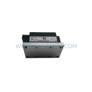
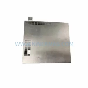
SKU: 4FD6303-0LA01-1A
Siemens 4FD6303-0LA01-1A Safety-Reliable Current Supply Module
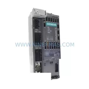
SKU: 6SL3040-0JA01-0AA0
Siemens 6SL3040-0JA01-0AA0 Safety-Reliable CU for Critical Control Sites
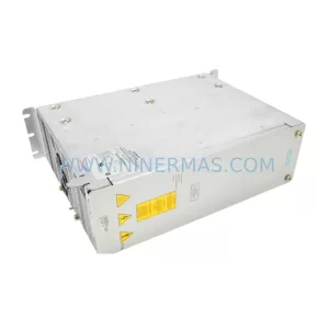
SKU: 6SE7032-7EB87-2DA1
SIEMENS 6SE7032-7EB87-2DA1 Spare Part for Industrial
Catalog Continuation
Alternative parts within PLC & Industrial Automation Modules.
Stay inside the same system family when you need substitutes, adjacent modules, or a broader shortlist for procurement review.
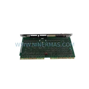
SKU: VT-VSPA1-1-12
REXROTH VT-VSPA1-1-12 Retrofit-Compatible Analog Amplifier
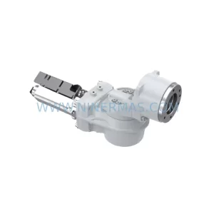
SKU: 00-170-819 00-170-819 00-187-547 00-187-547 00-176-109 RV-410F-236
KUKA RV-410F-236 Retrofit-Compatible Gearbox for Legacy Systems
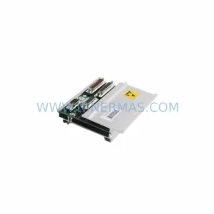
SKU: 3HAC044168-001
ABB 3HAC044168-001 Service-Ready Spare Part for IRC5 Drive