Original Industrial Spare Part
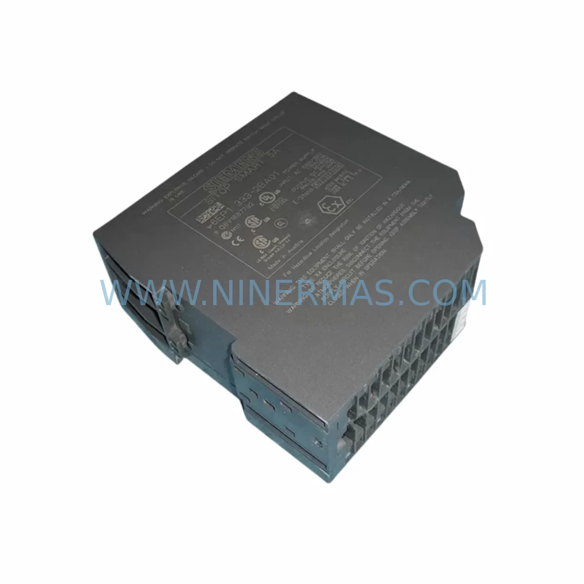
Siemens 6EP1333-2BA01 Retrofit-Ready DC Power Supply
Verify the part, confirm the platform family, and move straight into quotation with the right commercial details.
RFQ Ready
- SKU6EP1333-2BA01
- CategoryPLC & Industrial Automation Modules
- BrandSiemens
- SupportAvailability, lead time, condition, and shipping coordination
How Buyers Usually Use This Page
- Confirm the exact part number and platform family before sending the quote request.
- Use direct email when quantity, condition, and destination are already defined internally.
- Switch to the broader brand or category archive when you need alternates nearby.
Series Navigation
Move through the most common platform families behind this part.
Product RFQ
Send this part directly for quotation.
Include quantity, required condition, destination country, and target delivery timing. Current reference: Siemens 6EP1333-2BA01 Retrofit-Ready DC Power Supply with SKU 6EP1333-2BA01.
Siemens 6EP1333-2BA01 Retrofit-Ready DC Power Supply for Legacy Control Systems
The Siemens 6EP1333-2BA01 is a 24 VDC stabilized power supply module from the SITOP series, engineered for continuous-duty industrial environments. With an output current of 5 A and a wide-range AC input (120–230 V AC), this unit is a direct retrofit candidate for aging Siemens S5, S7-300, and S7-400 control panels where the original PSU has reached end-of-life or is no longer available through standard distribution channels. Its compact DIN-rail form factor and screw-terminal wiring interface allow engineers to replace a failed or obsolete power supply without modifying the existing cabinet layout, minimizing both engineering hours and unplanned downtime.
In legacy automation environments, the power supply is often the first component to degrade. Capacitor aging, thermal cycling, and voltage ripple accumulation cause gradual output instability that can corrupt PLC logic, trigger spurious I/O faults, or cause communication dropouts on PROFIBUS DP or MPI networks. Replacing the 6EP1333-2BA01 — or its predecessors — with a verified, pre-tested unit restores stable 24 VDC rail voltage and protects downstream modules including the CPU 315-2 DP, SM 321 digital input modules, SM 331 analog input modules, and IM 360/361 interface modules used in multi-rack S7-300 configurations.
Upgrade Compatibility Table
| Parameter | 6EP1333-2BA01 Specification | Retrofit Notes |
|---|---|---|
| Input Voltage | 120 / 230 V AC (wide range) | Compatible with standard single-phase industrial supply; no transformer required in most EU/Asia installations |
| Output Voltage | 24 V DC (stabilized) | Direct replacement for 24 VDC SITOP predecessors; verify load rail voltage before energizing |
| Output Current | 5 A continuous | Confirm total I/O and CPU current draw does not exceed 5 A; add SITOP expansion module if required |
| Mounting | 35 mm DIN rail | Standard TS 35 rail; fits existing S7-300 mounting rails without modification |
| Terminal Type | Screw terminals | Re-use existing wire ferrules; verify torque spec (0.5–0.6 Nm) during re-termination |
| PROFIBUS / MPI Compatibility | Indirect (stable 24 VDC rail) | Stable PSU output is prerequisite for reliable PROFIBUS DP and MPI communication |
| Protection Class | IP20 | Suitable for enclosed control cabinet installation; add IP54 enclosure for harsh-environment deployment |
| Replacement Path | Replaces 6EP1333-1AL12, 6EP1333-2AA01 | Verify terminal layout and output current rating before substitution |
| Warranty | 12 Months | Covered from date of shipment; includes pre-shipment output voltage and load regulation test |
Retrofit Planning for Existing Automation Systems
A successful power supply retrofit begins with a full load audit of the existing 24 VDC rail. In a typical S7-300 rack, the combined current draw of the CPU module, digital I/O modules such as the SM 321 (DI 32×DC 24V) and SM 322 (DO 32×DC 24V), and analog modules such as the SM 331 (AI 8×12Bit) can approach or exceed 4 A under full load. If the existing cabinet also powers field devices — proximity sensors, solenoid valves, or indicator lamps — through the same 24 VDC bus, the 6EP1333-2BA01’s 5 A output may need to be supplemented with a SITOP PSU8200 expansion or a secondary SITOP modular 10 A unit on a separate DIN rail section.
For multi-rack S7-300 systems using IM 360 and IM 361 interface modules, each expansion rack requires its own dedicated power supply. The 6EP1333-2BA01 is well-suited for powering individual expansion racks where the I/O load is moderate. Engineers should document the current draw of each rack independently and size the replacement PSU accordingly before ordering.
When the control system also includes an OP 7, OP 17, or TP 177B HMI panel connected via MPI, the HMI’s 24 VDC supply should be verified as a separate branch circuit. A shared PSU that is undersized or degraded will cause intermittent HMI communication faults that are often misdiagnosed as CPU or network issues. Replacing the 6EP1333-2BA01 with a verified unit and separating the HMI supply branch eliminates this failure mode.
For systems migrating from PROFIBUS DP to PROFINET, the power supply retrofit is typically performed in parallel with the network upgrade. The CP 343-1 PROFINET communication processor and the IE FC RJ45 Plug 180 connectors used in the new network segment both require stable 24 VDC supply. Ensuring the 6EP1333-2BA01 is replaced before the network cutover prevents voltage-related packet loss during the commissioning phase of the PROFINET migration.
In cabinets where a Siemens LOGO! 8 or LOGO! 230RCE is used for auxiliary control logic — such as lighting circuits, pump sequencing, or door interlock monitoring — the LOGO! module’s 24 VDC input should be sourced from the same stabilized rail. Confirm that the total auxiliary load does not push the 6EP1333-2BA01 beyond its rated 5 A output. If it does, a dedicated SITOP PSA100S selective circuit protection module can be added to isolate and protect individual load branches without requiring a larger PSU.
Programming cable compatibility is another consideration during retrofit. If the site uses a PC Adapter USB A2 or MPI/PROFIBUS adapter for online diagnostics and program backup, these adapters draw their operating power from the USB port of the programming laptop, not from the 24 VDC rail. However, the CPU itself must be powered and in RUN or STOP mode for a successful online connection. Confirming that the replacement 6EP1333-2BA01 is energized and within output voltage tolerance before connecting the programming cable prevents false communication errors during the backup and restore procedure.
Downtime Control During System Migration
Minimizing production downtime during a power supply replacement requires a structured pre-outage preparation sequence. Before the planned maintenance window, the site engineer should perform a full online backup of the S7-300 CPU program using STEP 7 v5.x or TIA Portal in offline mode, saving the project to a local drive and a secondary backup location. The CPU’s current operating mode (RUN-P or RUN) and any active force tables or variable monitoring sessions should be documented so they can be restored immediately after the replacement.
During the outage, the recommended sequence is: (1) switch the CPU to STOP mode via the mode selector switch or STEP 7 online interface; (2) de-energize the cabinet at the main circuit breaker; (3) photograph the existing terminal wiring on the 6EP1333-2BA01 before disconnecting any conductors; (4) remove the failed or end-of-life PSU from the DIN rail; (5) install the replacement 6EP1333-2BA01, re-terminate all conductors to the correct terminals using the original wiring photograph as reference; (6) re-energize the cabinet and verify 24 VDC output voltage at the PSU terminals before reconnecting the load rail; (7) switch the CPU back to RUN mode and confirm that all I/O modules return to their expected states within the first scan cycle.
For systems where a cold restart is not acceptable — such as continuous process lines or safety-instrumented systems — a hot-standby power supply configuration using a SITOP UPS1600 uninterruptible power supply module can bridge the 24 VDC rail during the PSU swap, maintaining CPU power and preserving the current program state throughout the replacement procedure. This approach reduces the effective production outage to under two minutes in most cabinet configurations.
After re-energization, the engineer should monitor the 24 VDC output voltage under full load for a minimum of 15 minutes using a calibrated multimeter or the SITOP PSU diagnostics interface, confirming that output voltage remains within the ±1% regulation band specified for the 6EP1333-2BA01. Any deviation outside this band indicates a wiring error, an overloaded output, or a fault in the replacement unit and should be investigated before returning the system to automatic production mode.
Retrofit Support FAQ
Q1: Is the 6EP1333-2BA01 a direct replacement for the 6EP1333-2AA01 and 6EP1333-1AL12?
The 6EP1333-2BA01 shares the same 24 VDC / 5 A output rating and DIN-rail mounting footprint as the 6EP1333-2AA01 and is functionally compatible as a drop-in replacement in most S7-300 and S7-400 cabinet configurations. The 6EP1333-1AL12 is an older SITOP compact variant with a slightly different terminal layout; verify terminal positions against the original wiring diagram before substitution. All three units are pre-shipment tested for output voltage accuracy and load regulation before dispatch.
Q2: What commissioning checks are required after installing the replacement PSU?
After installation, verify: (a) output voltage at the PSU terminals (target: 24.0–24.5 VDC under no load); (b) output voltage at the CPU power connector under full rack load; (c) absence of the PSU’s overload or short-circuit LED indicator; (d) CPU transitions to RUN mode without fault; (e) all I/O modules report correct status in STEP 7 or TIA Portal hardware diagnostics. Document the measured output voltage in the site maintenance log for future reference.
Q3: Can the 6EP1333-2BA01 power both the S7-300 rack and a connected HMI panel simultaneously?
This depends on the combined current draw. A standard S7-300 CPU 315-2 DP rack with 8 mixed I/O modules typically draws 2.5–3.5 A. An OP 17 or TP 177B HMI panel adds approximately 0.5–0.8 A. The combined load of 3.0–4.3 A is within the 6EP1333-2BA01’s 5 A rating, but leaves limited headroom. For cabinets with additional field device loads on the same 24 VDC bus, a dedicated PSU for the HMI branch is recommended to prevent voltage droop under peak load conditions.
Q4: What warranty and stock availability does NINERMAS provide for the 6EP1333-2BA01?
NINERMAS supplies the 6EP1333-2BA01 with a 12-month warranty from the date of shipment. Each unit undergoes pre-shipment output voltage and load regulation testing before dispatch. Stock is maintained for immediate shipment to minimize lead times for urgent retrofit and breakdown replacement requirements. For volume orders or scheduled maintenance programs, contact our sales team to confirm availability and lead time.
| Product Series | SITOP |
|---|---|
| Country of Origin | DE |
Catalog Continuation
More Siemens modules in the catalog.
Use the brand lane to compare nearby part numbers, platform-adjacent modules, and other inquiry-ready listings before sending your final RFQ.
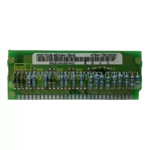
SKU: 6SE7038-6EK84-1BH0
Siemens 6SE7038-6EK84-1BH0 Retrofit Drive Control Module
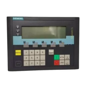
SKU: 6SL3055-0AA00-4CA5
Siemens 6SL3055-0AA00-4CA5 Retrofit-Compatible Operator Panel for Legacy Systems
Catalog Continuation
Alternative parts within PLC & Industrial Automation Modules.
Stay inside the same system family when you need substitutes, adjacent modules, or a broader shortlist for procurement review.
SKU: OZDPROFI12MG12
Hirschmann OZDPROFI12MG12 Spare Part for Industrial Maintenance
SKU: 07025-0000-70-1-04
KONTRON 07025-0000-70-1-04 Service-Ready Spare Part