Original Industrial Spare Part
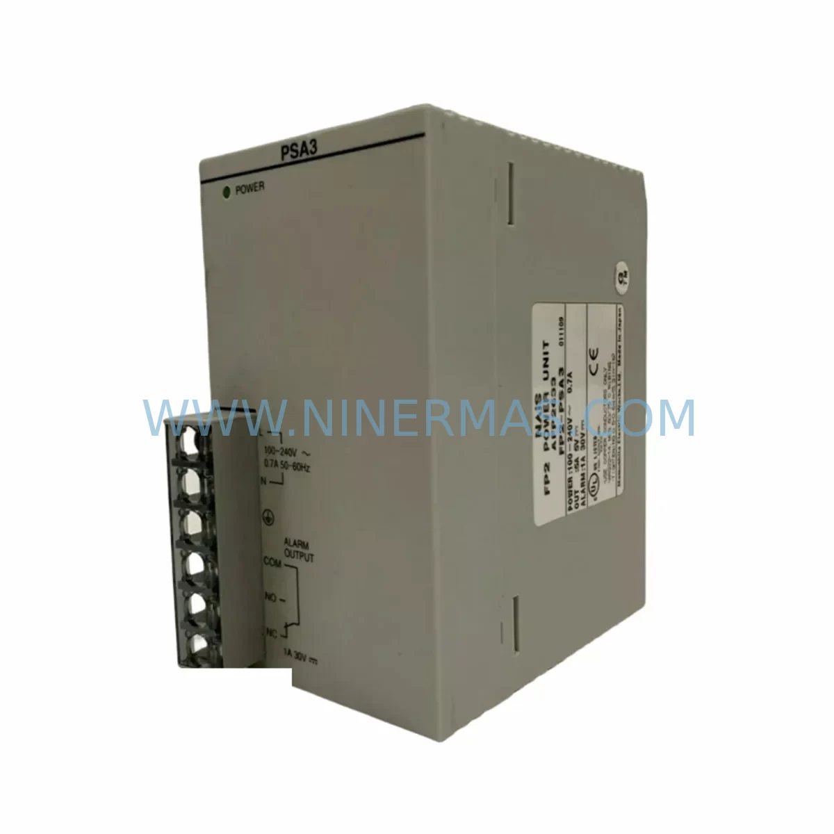
Panasonic FP2-PSA3 Retrofit-Compatible Power Supply for Legacy Systems
Verify the part, confirm the platform family, and move straight into quotation with the right commercial details.
RFQ Ready
- SKUFP2-PSA3
- CategoryPLC & Industrial Automation Modules
- BrandPanasonic
- SupportAvailability, lead time, condition, and shipping coordination
How Buyers Usually Use This Page
- Confirm the exact part number and platform family before sending the quote request.
- Use direct email when quantity, condition, and destination are already defined internally.
- Switch to the broader brand or category archive when you need alternates nearby.
Series Navigation
Move through the most common platform families behind this part.
Product RFQ
Send this part directly for quotation.
Include quantity, required condition, destination country, and target delivery timing. Current reference: Panasonic FP2-PSA3 Retrofit-Compatible Power Supply for Legacy Systems with SKU FP2-PSA3.
Panasonic FP2-PSA3 Retrofit-Compatible Power Supply for Legacy Systems
The Panasonic FP2-PSA3 is a dedicated AC power supply module engineered for the FP2 Series programmable logic controller platform — one of Panasonic’s most widely deployed mid-range PLC families in process automation, machine control, and building management applications. As production lines age and original FP2 system components approach or exceed their published service life, the FP2-PSA3 remains a critical retrofit and replacement component for engineers tasked with extending the operational lifespan of existing control architectures without committing to a full system overhaul.
For maintenance teams managing legacy control cabinets, the FP2-PSA3 delivers the precise voltage regulation and current capacity required to sustain stable operation of FP2 backplane assemblies, I/O expansion racks, and connected field devices. Its compatibility with the standard FP2 rack mounting system — including the FP2-BP08 and FP2-BP16 backplane units — means that replacement can be executed without structural modification to the control cabinet, significantly reducing downtime exposure during planned or emergency maintenance windows.
When evaluating the FP2-PSA3 as a replacement for a failed or degraded power supply in an existing installation, engineers should verify the total current draw of all installed modules on the backplane. A typical FP2 rack may include a combination of digital input modules such as the FP2-X32, digital output modules such as the FP2-Y32T, and analog I/O modules such as the FP2-AD4 or FP2-DA2. Each of these modules contributes to the aggregate DC bus load, and the FP2-PSA3 must be confirmed as adequate for the installed configuration before commissioning the replacement unit.
In retrofit scenarios where the original FP2 CPU module — such as the FP2-C1 or FP2-C2 — remains in service, the power supply replacement is typically the lowest-risk intervention available. The CPU retains its resident program in non-volatile memory, and no re-programming is required following a power supply swap, provided the CPU is not powered down for an extended period that would drain the backup battery. Engineers should confirm battery status on the CPU module prior to initiating the power supply replacement and replace the lithium backup cell if its voltage is marginal.
For installations that include communication modules — such as the FP2-ET1 Ethernet unit or FP2-SX1 serial communication module — the power supply replacement sequence must account for the re-initialization time of these modules following power restoration. SCADA systems and HMI panels connected via Modbus RTU, MEWTOCOL, or Ethernet/IP should be configured to tolerate a brief communication interruption during the switchover. Operators should coordinate with the control room to suppress nuisance alarms during the maintenance window and confirm that all communication links are re-established before returning the system to automatic mode.
In control cabinet upgrade projects where the FP2-PSA3 is being installed as part of a broader modernization effort — for example, alongside the addition of new FP2-X16Y16T mixed I/O modules or the integration of a FP2-PG1 pulse output module for servo axis control — the power budget must be recalculated to reflect the increased load. This is particularly important in cabinets where the original power supply was already operating near its rated capacity. The FP2-PSA3 should be treated as a known-good baseline from which the expanded system is designed, rather than assumed to be adequate without verification.
Terminal wiring compatibility is another key consideration during FP2-PSA3 replacement. The module uses a standard screw-terminal AC input block, and the existing field wiring — including the line, neutral, and protective earth conductors — can typically be reconnected directly to the replacement unit without modification. Engineers should inspect the condition of the terminal block on the failed unit and confirm that no thermal damage or conductor degradation has occurred before reusing the existing wiring. Where wiring condition is uncertain, replacement with appropriately rated conductors is recommended prior to energizing the new module.
Ninermas maintains verified stock of the FP2-PSA3 and supports global shipping with pre-shipment functional testing. Each unit is supplied with a 12-month warranty covering manufacturing defects and operational failures under normal service conditions. For time-critical maintenance situations, expedited dispatch is available upon request.
Upgrade Compatibility Table
| Parameter | Details |
|---|---|
| SKU / Part Number | FP2-PSA3 |
| Brand / Series | Panasonic / FP2 Series |
| Module Type | AC Power Supply Module |
| Compatible Backplanes | FP2-BP08, FP2-BP16 |
| Compatible CPUs | FP2-C1, FP2-C2 |
| AC Input | 100–240 VAC, 50/60 Hz (verify nameplate) |
| Mounting | Standard FP2 rack slot — no structural modification required |
| Terminal Wiring | Screw-terminal AC input block; existing field wiring reusable |
| Communication Compatibility | Supports FP2-ET1 (Ethernet), FP2-SX1 (Serial); re-init required after power cycle |
| Replacement Scope | Direct drop-in for failed or degraded FP2 power supply units |
| Retrofit Recommendation | Verify total module current draw before installation; recalculate if I/O expanded |
| Commissioning Note | Confirm CPU backup battery voltage before power supply swap |
| Warranty | 12 Months — manufacturing defects and operational failures under normal service |
| Pre-Shipment Testing | Functional test performed on each unit before dispatch |
| Origin | Japan |
Retrofit Planning for Existing Automation Systems
A successful FP2-PSA3 retrofit begins with a thorough audit of the existing control cabinet. The engineer should document all installed modules on each backplane, recording the model number, slot position, and rated current consumption of each unit. In a typical FP2 installation, this audit will identify a mix of digital and analog I/O modules — commonly the FP2-X32 for 32-point digital input, the FP2-Y32T for transistor output, and the FP2-AD4 for 4-channel analog input — alongside the CPU and any installed communication or special function modules.
Where the retrofit scope extends beyond a simple power supply replacement to include I/O expansion — for example, adding FP2-X16Y16T mixed I/O modules to accommodate new field instruments — the power budget must be updated before the new supply is ordered. Similarly, if the project includes the addition of a FP2-PG1 pulse output module for stepper or servo axis control, or a FP2-SX1 serial communication module for integration with a new SCADA or HMI system, these loads must be factored into the supply selection.
For cabinets that include an HMI panel — such as a Panasonic GT series touch panel connected via MEWTOCOL-COM — the retrofit plan should include a communication link verification step. After the FP2-PSA3 is installed and the system is powered up, the engineer should confirm that the HMI is receiving valid data from the CPU and that all screen pages are displaying correctly. Any discrepancies in tag values or screen navigation should be investigated before the system is returned to production.
Signal isolators and terminal multipliers installed between the FP2 I/O modules and field instruments should also be inspected during the retrofit. These passive and active components are often overlooked during power supply replacements but can be a source of latent faults that manifest after the system is returned to service. Confirming the integrity of the signal chain from field sensor through isolator to I/O module is a best practice that reduces the risk of post-retrofit nuisance trips.
Programming cable access — typically via a USB-to-RS232 adapter and Panasonic’s FPWIN Pro or FPWIN GR software — should be arranged prior to the maintenance window so that the engineer can perform a live program verification after the power supply replacement. Comparing the online program state against the archived backup confirms that no data corruption occurred during the power interruption and provides a documented baseline for future maintenance activities.
Downtime Control During System Migration
Minimizing downtime during an FP2-PSA3 replacement requires careful pre-planning and a disciplined execution sequence. The first step is to obtain a verified backup of the CPU program using FPWIN Pro or FPWIN GR, saved to a secure location independent of the control system. This backup serves as the recovery baseline in the unlikely event that the CPU memory is corrupted during the power interruption.
Before de-energizing the cabinet, the engineer should place the process under manual control at the field level where possible, isolating the automated sequences that depend on the FP2 outputs. This approach preserves production continuity for any sub-processes that can be operated manually and limits the scope of the shutdown to the control system itself rather than the entire production line.
The physical replacement of the FP2-PSA3 is straightforward: the module is removed from the backplane slot, the AC input wiring is transferred to the replacement unit, and the new module is seated and secured. The total hands-on time for this operation is typically under fifteen minutes for an experienced engineer. The majority of the maintenance window is consumed by pre-work — program backup, manual mode transition, and communication link documentation — and post-work — power-up verification, communication link confirmation, HMI screen validation, and return to automatic mode.
For installations where even a brief interruption is operationally significant, a hot-standby strategy using a pre-staged replacement FP2-PSA3 — tested and confirmed functional before the maintenance window — eliminates the risk of discovering a defective replacement unit during the outage. Ninermas supports this approach by providing pre-shipment functional testing on all FP2-PSA3 units, ensuring that the replacement module is confirmed operational before it reaches the site.
After power restoration, the engineer should monitor the system for a minimum of thirty minutes before releasing it to automatic production mode. This observation period allows any latent issues — such as marginal I/O module behavior at the new supply voltage, communication link instability, or HMI data refresh anomalies — to manifest under controlled conditions rather than during unattended operation.
Retrofit Support FAQ
Q1: Is the FP2-PSA3 a direct drop-in replacement for all FP2 series power supply variants?
The FP2-PSA3 is the AC input power supply variant for the FP2 platform. Before ordering, confirm that your existing installation uses an AC input supply rather than a DC input variant. The backplane connector and slot dimensions are standardized across the FP2 power supply family, but the input voltage specification must match the site supply. Review the nameplate of the failed unit and confirm the AC input voltage range before proceeding.
Q2: What pre-shipment testing does Ninermas perform on the FP2-PSA3?
Each FP2-PSA3 unit dispatched by Ninermas undergoes functional testing prior to shipment. This includes energization at rated input voltage, verification of DC output regulation under load, and inspection of the terminal block and module connector. Units that do not meet specification are quarantined and not dispatched. A 12-month warranty is provided on all units covering manufacturing defects and operational failures under normal service conditions.
Q3: Can the FP2-PSA3 support an expanded I/O configuration beyond the original installation?
The FP2-PSA3 has a defined rated output current capacity. If the retrofit project includes the addition of new I/O modules — such as analog input modules, pulse output modules, or communication modules — the total current draw of the expanded configuration must be calculated and compared against the FP2-PSA3 rated output. If the expanded load exceeds the supply rating, a higher-capacity power supply variant should be selected. Ninermas technical support can assist with power budget calculations upon request.
Q4: What is the recommended procedure if the CPU program is lost after the power supply replacement?
If the FP2 CPU — such as the FP2-C1 or FP2-C2 — loses its program following a power supply replacement, the most common cause is a depleted backup battery that was unable to sustain memory during the power interruption. The recovery procedure is to restore the program from the pre-maintenance backup using FPWIN Pro or FPWIN GR via the programming cable, then perform a full I/O check before returning the system to automatic mode. To prevent recurrence, replace the CPU backup battery as part of every power supply maintenance activity.
| Product Series | Legacy |
|---|
Catalog Continuation
More Panasonic modules in the catalog.
Use the brand lane to compare nearby part numbers, platform-adjacent modules, and other inquiry-ready listings before sending your final RFQ.

SKU: ZUEP5585D 0.17KW MG_03_40_60 00-201-179 cloos pcif 033.59.20.00
Panasonic ZUEP5585D Retrofit Servo Drive for Legacy Systems
SKU: MT-9-5.4-002LB MQMA022P2B 0150-76217 0100-01907 0100-20458
Panasonic MQMA022P2B Retrofit Servo Motor for Legacy Systems
Catalog Continuation
Alternative parts within PLC & Industrial Automation Modules.
Stay inside the same system family when you need substitutes, adjacent modules, or a broader shortlist for procurement review.