Original Industrial Spare Part
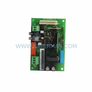
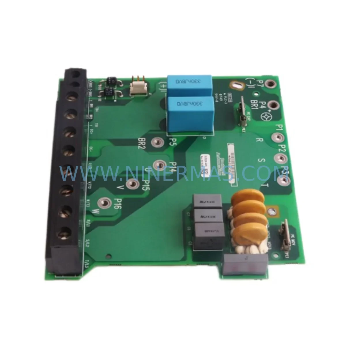
Allen-Bradley 315116-A05 Retrofit-Compatible Drive Board
Verify the part, confirm the platform family, and move straight into quotation with the right commercial details.
RFQ Ready
- SKU315116-A05
- CategoryPLC & Industrial Automation Modules
- BrandAllen-Bradley
- SupportAvailability, lead time, condition, and shipping coordination
How Buyers Usually Use This Page
- Confirm the exact part number and platform family before sending the quote request.
- Use direct email when quantity, condition, and destination are already defined internally.
- Switch to the broader brand or category archive when you need alternates nearby.
Series Navigation
Move through the most common platform families behind this part.
Product RFQ
Send this part directly for quotation.
Include quantity, required condition, destination country, and target delivery timing. Current reference: Allen-Bradley 315116-A05 Retrofit-Compatible Drive Board with SKU 315116-A05.
Allen-Bradley 315116-A05 Retrofit-Compatible Drive Board for Legacy Systems
The Allen-Bradley 315116-A05 is a drive control board designed for the PowerFlex 700 series AC drive platform — one of the most widely deployed variable frequency drive families in industrial automation. As legacy PowerFlex 700 installations age and original boards reach end-of-life, the 315116-A05 serves as a critical retrofit component enabling maintenance engineers to restore full drive functionality without replacing the entire drive chassis. Whether you are managing a planned upgrade cycle or responding to an unplanned fault, this board provides a reliable, tested, and warranty-backed path to system recovery.
For facilities running PowerFlex 700 drives in continuous production environments — including conveyor systems, pump stations, compressor banks, HVAC air handling units, and material handling lines — the 315116-A05 addresses the most common failure mode: control board degradation caused by thermal cycling, capacitor aging, and transient voltage stress. Replacing this board restores the drive’s ability to execute speed reference commands, manage acceleration/deceleration ramps, and communicate with upstream controllers via the drive’s native communication interface.
Upgrade Compatibility Table
| Parameter | Details |
|---|---|
| SKU | 315116-A05 |
| Brand | Allen-Bradley |
| Series | PowerFlex 700 |
| Component Type | Drive Control / Gate Driver Board |
| Compatible Drive Frame | PowerFlex 700 Frame 3–6 (verify frame size before ordering) |
| Interface | Internal backplane connector; matches OEM board footprint |
| Communication Compatibility | Compatible with EtherNet/IP, DeviceNet, and ControlNet adapter modules installed in the drive |
| Replacement Scope | Direct board swap; no chassis modification required |
| Commissioning Requirement | Parameter restore from backup or manual re-entry via HIM or DriveExplorer/Studio 5000 |
| Installation Environment | IP20 enclosure; standard industrial panel conditions |
| Pre-Shipment Testing | Functional test performed before dispatch |
| Warranty | 12 Months |
Retrofit Planning for Existing Automation Systems
A successful 315116-A05 board replacement requires more than simply swapping the hardware. Maintenance engineers should approach this as a structured retrofit event, beginning with a full review of the drive’s parameter file. If a Human Interface Module (HIM) — such as the 20-HIM-A6 or 20-HIM-C6S — is installed, use it to upload the existing parameter set before powering down the drive. This backup is essential for restoring motor nameplate data, speed references, torque limits, and fault response configurations after the board is replaced.
Before removing the 315116-A05 board, verify the incoming AC supply voltage at the drive’s input terminals and confirm that the 24VDC control power supply feeding the drive’s logic circuits is within specification. Many PowerFlex 700 installations share a common 24VDC bus with other field devices, and a marginal power supply can cause intermittent faults on a newly installed board. Check the 1606-XLP or equivalent 24VDC power supply output under load before proceeding.
Inspect the drive’s I/O terminal block wiring — including analog speed reference inputs (0–10V or 4–20mA), digital start/stop commands, and fault relay outputs — and document all connections before disconnecting. In multi-drive panels, it is common for terminal numbering to drift from original drawings over years of field modifications. Confirm that the wiring matches the current drive parameter configuration for input mode and scaling.
If the drive communicates with a ControlLogix or CompactLogix PLC via an EtherNet/IP communication adapter (such as the 20-COMM-E), verify that the adapter’s IP address and drive tag mappings in the Logix program are documented. After board replacement, the communication adapter typically retains its configuration, but the drive’s node address and network parameters should be confirmed before returning the system to automatic mode.
For drives connected to a DeviceNet network via a 20-COMM-D adapter, check the node address switch settings on the adapter and confirm the scanner’s I/O connection size matches the drive’s configured data format. A mismatch here will prevent the drive from going online after the retrofit, adding unnecessary downtime.
In installations where the PowerFlex 700 is mounted in a MCC (Motor Control Center) bucket or a custom control cabinet alongside other Allen-Bradley components — such as a 1756 ControlLogix chassis, 1734 POINT I/O modules, or a PanelView Plus HMI — coordinate the retrofit window to allow time for a full system restart and verification sequence. Do not assume the drive will return to automatic operation without a supervised commissioning step.
Finally, inspect the drive’s internal DC bus capacitors and gate driver components for signs of physical damage or discoloration. If the original board failure was caused by a DC bus overvoltage event, the IGBTs and snubber circuits may also require inspection before the replacement board is powered up.
Downtime Control During System Migration
Minimizing downtime during a 315116-A05 board replacement depends on preparation quality. The single most effective measure is having a pre-tested replacement board on-site before the fault occurs. For facilities running PowerFlex 700 drives in critical process roles — such as cooling tower fans, boiler feed pumps, or main conveyor drives — a spare board held in climate-controlled storage can reduce mean time to repair from days to hours.
When the replacement event is planned, schedule it during a scheduled maintenance window and prepare a step-by-step commissioning checklist that includes: power isolation and lockout/tagout verification, parameter backup confirmation, board removal and installation, wiring inspection, power restoration sequence, parameter restore, communication link verification, and a no-load test run before returning the motor to process load. This structured approach prevents the most common post-replacement issues: incorrect parameter restore, missed wiring reconnections, and communication adapter faults.
For legacy systems where the original drive parameters were never backed up, Ninermas can assist with parameter reconstruction based on motor nameplate data and application requirements. Contact our technical team before the replacement event to prepare a baseline parameter file that can be loaded immediately after board installation, further reducing commissioning time.
All 315116-A05 boards supplied by Ninermas are functionally tested prior to shipment and include a 12-month warranty covering manufacturing defects and operational failures under normal industrial operating conditions. Long-term supply availability is maintained to support ongoing maintenance programs and multi-site fleet management.
Retrofit Support FAQ
Q: Is the 315116-A05 a direct replacement for the original Allen-Bradley board in my PowerFlex 700 drive?
A: Yes, the 315116-A05 is designed as a direct board replacement for compatible PowerFlex 700 frame sizes. Confirm your drive’s frame size and catalog number before ordering to ensure full mechanical and electrical compatibility. No chassis modification is required for a standard board swap.
Q: Do I need to re-enter all drive parameters after replacing the board?
A: Yes. The control board does not retain parameter data independently. You will need to restore parameters from a backup file using a HIM, DriveExplorer, or Studio 5000 software. If no backup exists, parameters must be re-entered manually based on motor nameplate data and application requirements. Ninermas recommends performing a parameter backup before any board replacement event.
Q: How is the board tested before shipment?
A: Every 315116-A05 unit supplied by Ninermas undergoes functional testing prior to dispatch. This includes power-on verification and basic operational checks to confirm the board is free from manufacturing defects. A 12-month warranty is included with every unit.
Q: Can Ninermas supply multiple units for a fleet maintenance program?
A: Yes. Ninermas maintains stock of the 315116-A05 to support both emergency replacement and planned inventory programs. Volume orders and long-term supply agreements are available. Contact our team to discuss your fleet size and annual consumption requirements.
| Product Series | PowerFlex |
|---|---|
| Country of Origin | US |
Catalog Continuation
More Allen-Bradley modules in the catalog.
Use the brand lane to compare nearby part numbers, platform-adjacent modules, and other inquiry-ready listings before sending your final RFQ.
Catalog Continuation
Alternative parts within PLC & Industrial Automation Modules.
Stay inside the same system family when you need substitutes, adjacent modules, or a broader shortlist for procurement review.
SKU: 4060-00949 VV5Q11-10-X3105V UT-CNN-01 H1001426001A 3620-00122 CDN127-1
SMC VV5Q11-10-X3105V-4060-00949 Retrofit Valve Manifold