Original Industrial Spare Part
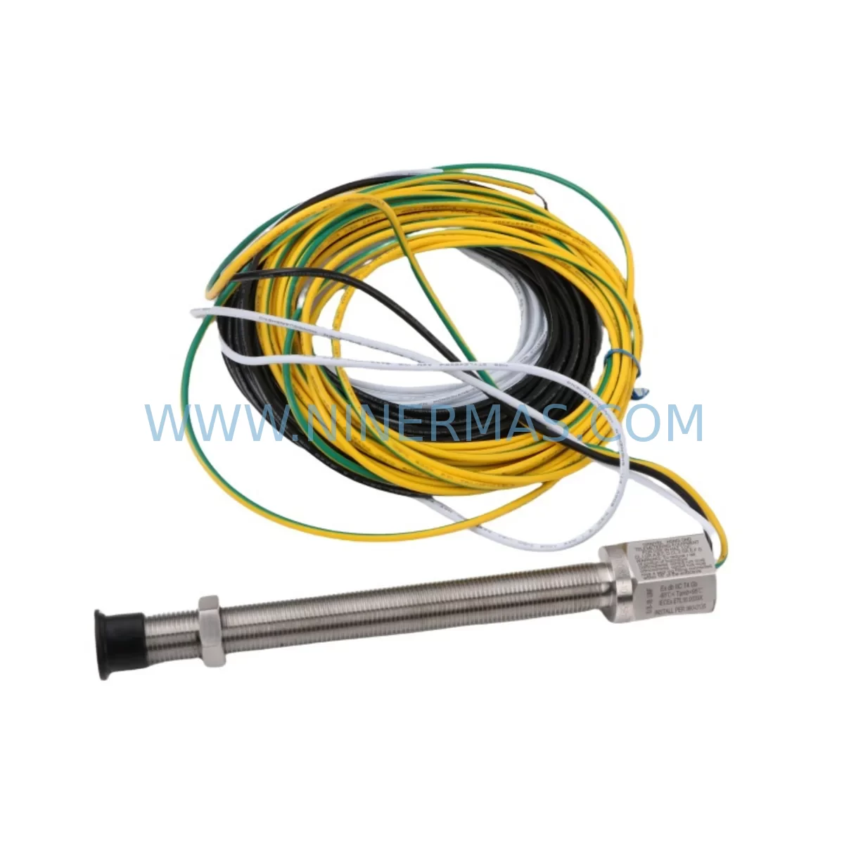
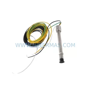
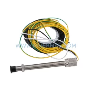
AI-Tek 70085-1010-205 Retrofit-Compatible Passive Speed Sensor
Verify the part, confirm the platform family, and move straight into quotation with the right commercial details.
RFQ Ready
- SKU70085-1010-205
- CategoryPLC & Industrial Automation Modules
- BrandAI-Tek
- SupportAvailability, lead time, condition, and shipping coordination
How Buyers Usually Use This Page
- Confirm the exact part number and platform family before sending the quote request.
- Use direct email when quantity, condition, and destination are already defined internally.
- Switch to the broader brand or category archive when you need alternates nearby.
Series Navigation
Move through the most common platform families behind this part.
Product RFQ
Send this part directly for quotation.
Include quantity, required condition, destination country, and target delivery timing. Current reference: AI-Tek 70085-1010-205 Retrofit-Compatible Passive Speed Sensor with SKU 70085-1010-205.
AI-Tek 70085-1010-205 Retrofit-Compatible Passive Speed Sensor for Legacy System Modernization
The AI-Tek 70085-1010-205 is a passive magnetic speed sensor engineered for industrial automation environments where legacy tachometer and speed feedback systems require a reliable, drop-in compatible replacement. As production lines age and original equipment manufacturers discontinue support for older sensing components, the 70085-1010-205 has become a critical retrofit solution for maintenance engineers and system integrators managing brownfield automation upgrades across manufacturing, power generation, paper mills, steel processing, and heavy-duty drive applications.
Unlike active sensors that require external power supply conditioning, the 70085-1010-205 operates as a self-generating passive device — producing a sinusoidal voltage output proportional to the rotational speed of a ferromagnetic target wheel or gear. This characteristic makes it directly compatible with a wide range of legacy PLC analog input modules, speed controllers, and drive feedback cards without requiring signal conditioning hardware changes during retrofit.
Upgrade Compatibility Table
| Parameter | AI-Tek 70085-1010-205 | Retrofit Notes |
|---|---|---|
| Sensor Type | Passive Magnetic (Variable Reluctance) | Compatible with existing VR sensor input circuits |
| Output Signal | Sinusoidal AC voltage | Direct replacement for legacy tach feedback wiring |
| Connector / Termination | 2-pin flying leads | Verify terminal polarity before reconnection |
| Thread / Mounting | Standard threaded body | Confirm thread pitch and probe depth against housing |
| Target Compatibility | Ferromagnetic gear/ring | Measure air gap; typically 0.25–1.5 mm |
| Operating Temperature | Industrial grade | Suitable for panel and field-mount environments |
| Communication Protocol | Analog signal (no protocol) | No firmware or protocol migration required |
| Replacement Scope | Direct OEM substitute | Replaces discontinued AI-Tek and equivalent VR sensors |
| Commissioning | Air gap + signal verification | Use oscilloscope or drive diagnostic tool to confirm output |
| Warranty | 12 Months | Covered by NINERMAS from date of shipment |
Retrofit Planning for Existing Automation Systems
When integrating the AI-Tek 70085-1010-205 into an existing control architecture, the retrofit scope typically extends beyond the sensor itself. Engineers must evaluate the full signal chain from the sensing point back to the controller. In many legacy installations, the speed feedback signal feeds directly into a drive speed reference card or an analog tachometer input on a DC drive controller — both of which must be verified for input impedance compatibility with the passive sensor’s output voltage range.
For systems using older Allen-Bradley 1771 or 1746 SLC 500 series analog input modules, the sinusoidal output of the 70085-1010-205 may require a signal conditioner or frequency-to-voltage converter module before interfacing with the PLC rack. In contrast, systems built around Siemens SINAMICS or MICROMASTER 440 drive platforms often include native VR sensor input terminals, allowing direct wiring without additional conditioning hardware.
Retrofit planners should also account for the power supply module feeding the control cabinet — particularly when adding signal conditioning hardware. A 24VDC DIN-rail power supply with adequate current headroom is essential to avoid voltage sag affecting other I/O modules in the same panel. If the cabinet houses a Siemens S7-300 or S7-400 CPU with an ET 200 distributed I/O rack, the addition of a frequency input module such as the SM 331 or a dedicated FM 350 counter module may be the most integration-efficient path.
For legacy systems using Modbus RTU or PROFIBUS DP communication backbones, the speed signal from the 70085-1010-205 is typically converted at the drive or local I/O level before being transmitted upstream — meaning the sensor replacement itself does not trigger any protocol migration. However, if the retrofit is part of a broader migration to PROFINET or EtherNet/IP, engineers should plan for gateway modules or updated communication cards in parallel with the sensor swap.
Installation space is another key consideration. The 70085-1010-205 uses a standard threaded probe body, and the replacement unit must fit within the existing sensor boss or bracket. Measure the available probe depth and confirm the thread engagement length before ordering. In tight machine housings — common in paper machine drives and rolling mill gearboxes — even a few millimeters of dimensional difference can prevent proper air gap setting. Always verify the gap specification against the target wheel tooth height and confirm signal amplitude at minimum operating speed using a portable oscilloscope or the drive’s built-in diagnostic display.
Downtime Control During System Migration
Minimizing unplanned downtime is the primary concern when replacing speed sensors on running production equipment. For the AI-Tek 70085-1010-205, the replacement procedure is straightforward when properly pre-staged, but several steps must be completed in sequence to protect the existing program logic and maintain control continuity.
Before shutdown, document the current speed feedback signal amplitude and frequency at normal operating speed using the drive’s diagnostic interface or an external meter. This baseline reading becomes your commissioning acceptance criterion after the new sensor is installed. Back up the PLC program — whether stored on a Siemens memory card, an Allen-Bradley 1784-CF64 CompactFlash card, or a laptop-connected programming terminal — before any wiring is disturbed.
During the physical swap, tag and photograph all terminal connections before disconnecting. The 70085-1010-205’s two-lead output is polarity-sensitive in some drive input circuits; reversing the leads may invert the speed signal phase, causing the drive to fault on startup. Reconnect to the original terminal designations and torque all screw terminals to specification.
After installation, perform a slow-speed jog to verify signal presence before commanding full-speed operation. Compare the measured output frequency against the expected value based on gear tooth count and shaft RPM. If the drive uses a closed-loop speed regulation mode, confirm that the PID speed loop re-stabilizes within the expected settling time. Any deviation from the pre-shutdown baseline should be investigated before returning the machine to production. With proper pre-staging, total downtime for a 70085-1010-205 replacement can typically be held to under two hours on accessible installations.
Retrofit Support FAQ
Q1: Is the AI-Tek 70085-1010-205 a direct replacement for my existing passive speed sensor?
In most cases, yes — provided your existing sensor is a variable reluctance (VR) type with a compatible thread size, connector configuration, and target wheel air gap range. Confirm the thread pitch, body diameter, and cable exit direction before ordering. NINERMAS can assist with cross-reference verification based on your existing part number or nameplate data.
Q2: Does replacing the sensor require any PLC program changes?
For a like-for-like passive sensor replacement, no program changes are typically required. The 70085-1010-205 produces the same signal type as the original VR sensor. If your retrofit involves changing from a passive to an active sensor type, or if you are migrating to a new drive platform, program modifications to the speed feedback scaling parameters may be necessary.
Q3: What commissioning steps are required after installation?
Set the air gap to the manufacturer’s specification (typically 0.25–1.5 mm depending on target wheel geometry). Power up the drive and perform a slow-speed jog. Verify signal output using the drive’s diagnostic screen or an oscilloscope. Confirm that the speed feedback reading matches the commanded reference within the drive’s tolerance band before returning to automatic operation.
Q4: What are the supply and warranty terms?
NINERMAS maintains stock of the AI-Tek 70085-1010-205 for immediate shipment. All units are covered by a 12-month warranty from the date of shipment, covering manufacturing defects under normal operating conditions. Pre-shipment functional testing is performed on request. Contact our team for lead time confirmation and volume pricing.
| Product Series | Other series |
|---|
Catalog Continuation
More AI-Tek modules in the catalog.
Use the brand lane to compare nearby part numbers, platform-adjacent modules, and other inquiry-ready listings before sending your final RFQ.
SKU: 70082-1000-021
AI-Tek 70082-1000-021 Safety-Reliable Passive Speed Sensor
SKU: 70084-1713-111
AI-Tek 70084-1713-111 Retrofit-Compatible Passive Speed Sensor
Catalog Continuation
Alternative parts within PLC & Industrial Automation Modules.
Stay inside the same system family when you need substitutes, adjacent modules, or a broader shortlist for procurement review.
SKU: 6FC5357-0BB12-0AE0
Siemens 6FC5357-0BB12-0AE0 Service-Ready Industrial Spare Part
SKU: 3BSE011790R1(PXHK401)
ABB 3BSE011790R1 PXHK401 Retrofit-Ready Communication Module