Original Industrial Spare Part
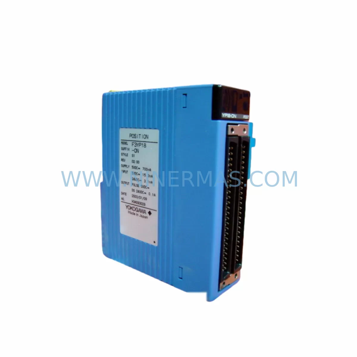
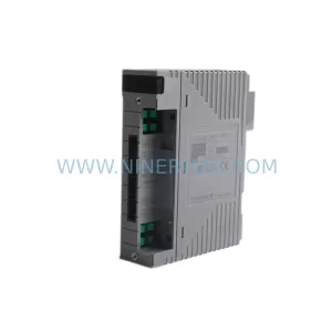
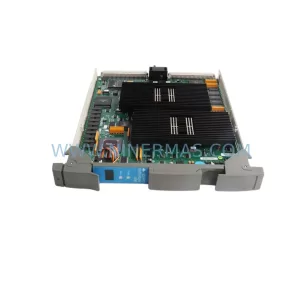
YOKOGAWA F3YP18-0N Retrofit-Compatible Output Module for Legacy Systems
Verify the part, confirm the platform family, and move straight into quotation with the right commercial details.
RFQ Ready
- SKUF3YP18-0N
- CategoryDCS Distributed Control Systems
- BrandYokogawa
- SupportAvailability, lead time, condition, and shipping coordination
How Buyers Usually Use This Page
- Confirm the exact part number and platform family before sending the quote request.
- Use direct email when quantity, condition, and destination are already defined internally.
- Switch to the broader brand or category archive when you need alternates nearby.
Series Navigation
Move through the most common platform families behind this part.
Product RFQ
Send this part directly for quotation.
Include quantity, required condition, destination country, and target delivery timing. Current reference: YOKOGAWA F3YP18-0N Retrofit-Compatible Output Module for Legacy Systems with SKU F3YP18-0N.
YOKOGAWA F3YP18-0N Retrofit-Compatible Output Module: Seamless Legacy System Modernization
The YOKOGAWA F3YP18-0N is a pulse/positioning output module designed for the FA-M3 programmable controller platform — one of Yokogawa’s most widely deployed industrial automation architectures across process manufacturing, utilities, and discrete production lines. As the FA-M3 series enters its extended lifecycle phase and many original modules approach end-of-availability, the F3YP18-0N has become a critical spare part for engineers managing legacy control systems, retrofit projects, and planned system migrations.
At NINERMAS, we maintain verified stock of the F3YP18-0N to support customers who need a direct replacement for failed or aging output modules — without forcing a full controller upgrade. Whether you are managing a brownfield retrofit, extending the operational life of an existing FA-M3 rack, or bridging toward a future migration to the STARDOM FCN/FCJ platform, this module provides the compatibility and reliability your application demands.
Upgrade Compatibility Table
| Parameter | F3YP18-0N Specification / Retrofit Notes |
|---|---|
| Module Type | Pulse / Positioning Output Module |
| Platform Compatibility | YOKOGAWA FA-M3 (F3 Series) — all standard base units and expansion racks |
| Backplane Interface | FA-M3 standard backplane bus; compatible with F3BU04-0N, F3BU08-0N, F3BU16-0N base units |
| Installation Slot | Any I/O slot on FA-M3 base unit or expansion rack; confirm slot addressing in ladder program |
| Communication Compatibility | Local bus only; no independent Ethernet/PROFIBUS port — relies on CPU module (e.g. F3SP71-4N, F3SP76-7N) for network communication |
| Replacement Fit | Direct drop-in for same-model failed units; verify terminal wiring map before swap |
| Wiring Terminals | Screw-type terminal block; confirm existing field wiring gauge and torque spec before reconnection |
| Power Consumption | Supplied via backplane; verify total rack power budget against F3PU20-0S or equivalent power supply module |
| Commissioning Requirement | Module address auto-assigned by slot position; confirm I/O map in FA-M3 ladder program (ToolBox or WideField3) |
| HMI Compatibility | Compatible with existing FAST/TOOLS, ProSafe-RS, or third-party HMI screens referencing FA-M3 I/O tags — no tag remapping required for direct replacement |
| Warranty | 12 Months — all NINERMAS-supplied spare parts carry a 12-month warranty from date of shipment |
Retrofit Planning for Existing Automation Systems
Replacing the F3YP18-0N within an active FA-M3 system requires careful pre-work to avoid unplanned downtime and protect existing program logic. The following planning checklist reflects the real-world steps engineers encounter during FA-M3 module replacement and partial system retrofits.
Power Budget Verification: Before inserting the replacement module, confirm that the rack’s power supply — typically an F3PU20-0S or F3PU28-0S power supply module — has sufficient headroom to support the F3YP18-0N alongside all other installed modules. Overloaded racks are a common cause of intermittent faults after module replacement.
Terminal Wiring Documentation: Photograph and document all existing field wiring on the terminal block before removal. The F3YP18-0N uses a screw-type terminal block; confirm wire gauge, shielding, and grounding practices match the original installation. In older installations, terminal labels may have faded — cross-reference the original engineering drawings or the FA-M3 hardware manual.
Backplane Slot and Module Address: The FA-M3 assigns I/O addresses based on physical slot position. If the replacement module is installed in the same slot as the failed unit, the address mapping in the ladder program (developed in WideField3 or the legacy ToolBox environment) remains valid. If the slot changes for any reason, the I/O map must be updated and the program re-downloaded to the CPU — typically an F3SP71-4N, F3SP76-7N, or equivalent FA-M3 CPU module.
Communication Link Integrity: The F3YP18-0N does not carry an independent communication port. All upstream communication — whether via Ethernet/IP, PROFIBUS-DP, or Modbus TCP — is handled by the CPU or dedicated communication modules such as the F3LE01-5T Ethernet interface module or F3LP02-0N PROFIBUS-DP module. Verify that these communication modules remain online and that the SCADA or DCS upstream (e.g. FAST/TOOLS historian) continues to receive valid data during the swap window.
HMI Screen Validation: After module replacement, validate all HMI faceplates and alarm pages that reference outputs driven by the F3YP18-0N. In systems using Yokogawa FAST/TOOLS or third-party SCADA platforms connected via OPC-DA/UA, confirm that output tag values are updating correctly and that no stale or forced values remain active from the pre-replacement troubleshooting phase.
I/O Expansion Considerations: If the retrofit is part of a broader I/O expansion — for example, adding new positioning axes or pulse outputs to an existing FA-M3 rack — confirm that the base unit (F3BU08-0N or F3BU16-0N) has available slots and that the total I/O count does not exceed the CPU’s scan capacity. In high-density installations, an additional F3BU16-0N expansion base unit connected via the FA-M3 expansion cable may be required.
Signal Isolation: In environments with high electrical noise — common in motor drive cabinets, welding lines, or variable-frequency drive (VFD) installations — consider adding signal isolators between the F3YP18-0N pulse outputs and the downstream servo amplifier or stepper driver. This protects the module from induced transients and extends service life in harsh environments.
Programming Cable and Backup: Before any module swap, connect a KM11-1 or USB-to-serial programming cable to the FA-M3 CPU and create a full program backup using WideField3. Store the backup offline. This ensures that if the CPU loses its program during power cycling (rare but possible in older battery-backed CPUs with degraded backup batteries), the program can be restored within minutes rather than hours.
Downtime Control During System Migration
For production environments where stopping the line is costly, the F3YP18-0N replacement can typically be completed within a planned maintenance window of 30–60 minutes, provided all pre-work has been completed in advance. The following practices help minimize risk and protect operational continuity:
- Pre-stage the replacement module at the control cabinet before the maintenance window begins. Confirm the module is the correct revision and that the terminal block wiring diagram is printed and on hand.
- Place the FA-M3 CPU in STOP mode via the key switch or WideField3 before removing the module. Do not hot-swap FA-M3 I/O modules unless the specific base unit and CPU revision explicitly support hot-swap operation — consult the hardware manual for your installed base unit model.
- Force outputs to safe state in the ladder program before stopping the CPU. This ensures that actuators, servo drives, and positioning systems connected to the F3YP18-0N pulse outputs are in a known, safe position before power is removed from the module.
- Verify module recognition after installation by checking the FA-M3 CPU’s I/O status display in WideField3. The replacement F3YP18-0N should appear as recognized in its assigned slot within seconds of CPU restart.
- Run a functional test in manual mode before returning the system to automatic operation. Jog each axis or output channel individually to confirm correct direction, pulse count, and limit switch response.
- Document the completed swap with date, module serial number, and technician name in the plant maintenance log. This supports future lifecycle planning and warranty tracking.
For customers planning a longer-term migration from FA-M3 to the STARDOM FCN-100 or FCN-500 platform, NINERMAS can advise on parallel-run strategies that allow the new controller to shadow the existing FA-M3 system before cutover, reducing migration risk and protecting existing process knowledge embedded in the ladder program.
Retrofit Support FAQ
Q1: Is the F3YP18-0N a direct drop-in replacement for a failed unit in my FA-M3 rack?
Yes — provided the replacement is installed in the same slot as the original module, no program changes are required. The FA-M3 assigns I/O addresses by slot position, so the existing ladder logic and HMI tag references remain valid. Confirm the terminal wiring before reconnecting field cables.
Q2: What commissioning steps are required after installing the replacement module?
After installation, restart the FA-M3 CPU and verify module recognition in WideField3 or the FA-M3 front panel display. Run a manual functional test on each output channel before returning to automatic mode. If the module is installed in a new slot (not the original), update the I/O address map in the ladder program and re-download to the CPU.
Q3: Does NINERMAS test modules before shipment?
Yes. All NINERMAS-supplied spare parts, including the F3YP18-0N, undergo pre-shipment functional verification. Each unit is shipped with a test record and is covered by a 12-month warranty from the date of shipment. If a module fails within the warranty period under normal operating conditions, NINERMAS will provide a replacement at no additional cost.
Q4: Can you supply the F3YP18-0N for long-term spare parts programs or blanket orders?
Yes. NINERMAS supports long-term procurement planning for discontinued and end-of-life Yokogawa FA-M3 components. We can hold dedicated stock against a blanket purchase order to ensure availability for planned maintenance shutdowns, insurance spares, and multi-site rollouts. Contact our team to discuss lead times, pricing, and stock commitment terms.
| Product Series | STARDOM |
|---|---|
| Country of Origin | JP |
Catalog Continuation
More Yokogawa modules in the catalog.
Use the brand lane to compare nearby part numbers, platform-adjacent modules, and other inquiry-ready listings before sending your final RFQ.
Catalog Continuation
Alternative parts within DCS Distributed Control Systems.
Stay inside the same system family when you need substitutes, adjacent modules, or a broader shortlist for procurement review.
SKU: PM632 3BSE005831R1
ABB PM632 3BSE005831R1 Retrofit-Compatible Processor for Legacy Systems
SKU: High Performance Communication Controller
Honeywell 51401635-150 Service-Ready Spare for C300