Original Industrial Spare Part
LTi Motion LSC-096-2-30-560-P5B0H2MM0 Retrofit Servo Drive
Verify the part, confirm the platform family, and move straight into quotation with the right commercial details.
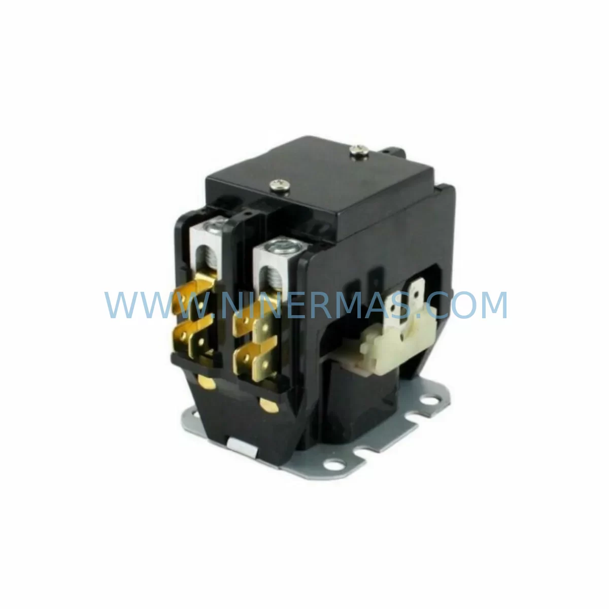
RFQ Ready
- SKULSC-096-2-30-560-P5B0H2MM0
- CategoryPLC & Industrial Automation Modules
- BrandLTI Motion
- SupportAvailability, lead time, condition, and shipping coordination
How Buyers Usually Use This Page
- Confirm the exact part number and platform family before sending the quote request.
- Use direct email when quantity, condition, and destination are already defined internally.
- Switch to the broader brand or category archive when you need alternates nearby.
Series Navigation
Move through the most common platform families behind this part.
Product RFQ
Send this part directly for quotation.
Include quantity, required condition, destination country, and target delivery timing. Current reference: LTi Motion LSC-096-2-30-560-P5B0H2MM0 Retrofit Servo Drive with SKU LSC-096-2-30-560-P5B0H2MM0.
LTi Motion LSC-096-2-30-560-P5B0H2MM0 Retrofit Servo Drive: Seamless Upgrade for Legacy Motion Control Systems
The LTi Motion LSC-096-2-30-560-P5B0H2MM0 is a high-performance servo drive from the LSC series, designed for precision motion control in demanding industrial environments. As original LSC series units approach end-of-life and OEM support is discontinued, plant engineers and maintenance teams face increasing pressure to source verified replacement units that can be installed without rewriting control logic or redesigning the control cabinet. This unit provides a direct retrofit path for legacy automation systems, preserving existing wiring, backplane configurations, and PLC program structures while restoring full drive functionality.
The LSC-096-2-30-560-P5B0H2MM0 designation encodes key electrical parameters: a 9.6 A continuous output current rating, a 2-axis or dual-channel configuration, a 30 A peak current capability, a 560 V DC bus voltage range, and a specific feedback and communication interface variant. These parameters are critical when cross-referencing against the original installation documentation to confirm drop-in compatibility before committing to a replacement order.
Upgrade Compatibility Table
| Parameter | LSC-096-2-30-560-P5B0H2MM0 | Retrofit Notes |
|---|---|---|
| Continuous Output Current | 9.6 A | Verify motor nameplate current does not exceed drive rating |
| DC Bus Voltage | 560 V DC | Confirm supply module output matches; check LSC power supply module compatibility |
| Peak Current | 30 A | Validate against motor stall and acceleration torque requirements |
| Feedback Interface | Encoder / Resolver (P5 variant) | Match encoder cable pinout; confirm resolver excitation frequency if applicable |
| Communication Protocol | SystemBus / Serial (MM0 variant) | Verify PLC communication card and baud rate settings before commissioning |
| Backplane / Rack Interface | LSC series backplane connector | Confirm rack slot width and connector alignment with existing LSC chassis |
| Installation Footprint | Standard LSC module width | Measure cabinet DIN rail space; no mechanical modification required for same-series swap |
| Commissioning Tool | DriveManager software | Use existing parameter backup file; upload and verify axis parameters after installation |
| Replacement Compatibility | Direct drop-in for LSC-096 variants | Cross-check full part number suffix before ordering |
| Warranty | 12-Month Warranty | Covered from date of shipment; includes functional and electrical testing |
Retrofit Planning for Existing Automation Systems
Successful retrofit of the LSC-096-2-30-560-P5B0H2MM0 into an existing control system requires a structured pre-installation review. Begin by auditing the current control cabinet layout to confirm available slot positions within the LSC series rack. The LSC series backplane distributes DC bus power and communication signals across all installed drive modules, so the physical slot assignment directly affects axis addressing in the PLC program. If the original unit occupied a specific slot, the replacement must be installed in the same position to avoid axis remapping in the controller.
Power capacity is the next critical checkpoint. The LSC power supply module feeding the rack must have sufficient headroom to support the 9.6 A continuous and 30 A peak demand of this drive alongside all other axes in the same rack. In multi-axis cabinets running LSC-050-2-30-560 or LSC-140-2-30-560 drives on adjacent slots, the cumulative peak current demand during simultaneous acceleration cycles must remain within the supply module’s rated output. If the existing supply module is already operating near its limit, a supply upgrade or load-sharing configuration may be required before the retrofit can proceed safely.
Encoder and resolver feedback wiring must be verified at the terminal level. The P5 feedback variant of this drive uses a specific encoder cable pinout that must match the motor’s feedback device. When replacing a failed unit, inspect the existing encoder cable for continuity and shielding integrity before reusing it. A damaged or improperly shielded encoder cable is a common source of position feedback errors after drive replacement. If the motor uses a resolver, confirm the excitation frequency and transformation ratio are compatible with the drive’s internal resolver interface.
Communication link integrity is equally important. The MM0 communication variant interfaces with the system controller via the LSC SystemBus or serial communication channel. Before powering the replacement drive, confirm that the communication card installed in the PLC or motion controller — such as a PROFIBUS DP communication module or a SystemBus interface card — is correctly configured for the axis address assigned to this drive. Baud rate, node address, and telegram type must match the original configuration. Use the existing DriveManager parameter backup file to restore axis-specific settings including current limits, speed ramps, position loop gains, and fault response parameters.
HMI screen references tied to this axis should also be reviewed. If the original system uses an operator panel or SCADA interface that displays drive status, fault codes, or axis position data, verify that the data source addresses remain valid after the replacement. In some legacy systems, drive fault codes are mapped to specific HMI alarm pages, and a firmware version difference between the original and replacement unit may alter the fault code numbering. Document any discrepancies and update the HMI alarm table accordingly.
Signal isolation between the drive’s analog reference inputs and the PLC analog output module should be confirmed, particularly in older installations where signal isolators or barrier modules were used to protect against ground loops. If the original installation included a signal isolator between the speed reference output and the drive’s analog input terminal, ensure the replacement drive’s input impedance is compatible with the isolator’s output specification.
Finally, confirm that the installation space within the control cabinet allows for adequate airflow around the replacement module. LSC series drives rely on forced-air or convection cooling depending on the cabinet configuration. Blocked ventilation slots or insufficient clearance between modules can cause thermal derating or premature shutdown during high-load cycles.
Downtime Control During System Migration
Minimizing production downtime during a servo drive replacement requires preparation that begins well before the maintenance window. The most effective approach is to complete all pre-installation verification steps — parameter backup, wiring documentation, communication configuration review, and spare parts staging — while the original drive is still operational or immediately after it fails, before the replacement unit arrives on site.
When the replacement LSC-096-2-30-560-P5B0H2MM0 arrives, perform a visual inspection and confirm the full part number matches the order. Power the unit on a bench test fixture if available, using a compatible LSC power supply module and a test motor or resistive load, to verify basic drive functionality before installation. This pre-installation functional test eliminates the risk of discovering a transit-damaged unit only after the production line has been taken offline.
During the actual swap, follow a structured sequence: isolate and lock out the DC bus supply, discharge the bus capacitors fully before touching any terminals, remove the failed unit, install the replacement in the same rack slot, reconnect encoder cable and motor power leads using the original wiring documentation, restore communication connections, and power up in a controlled sequence. Upload the parameter backup file via DriveManager before enabling the drive output. Run the axis through a low-speed jog cycle to confirm position feedback direction, velocity loop response, and fault-free operation before returning the machine to automatic mode.
Keeping a documented retrofit checklist specific to the LSC series — covering DC bus discharge confirmation, encoder cable continuity check, communication node address verification, parameter file upload, and test cycle sign-off — reduces the risk of commissioning errors and provides a traceable record for maintenance logs. This structured approach consistently achieves drive replacement completion within a single planned maintenance shift, protecting production schedules and reducing the financial impact of unplanned downtime.
Retrofit Support FAQ
Q: Is the LSC-096-2-30-560-P5B0H2MM0 a direct replacement for my existing LSC-096 unit?
A: In most cases, yes — provided the full part number suffix matches your original unit. The suffix encodes feedback type, communication variant, and hardware revision. Cross-check the complete part number from your original drive’s nameplate against the replacement unit before installation. If the suffix differs, contact our technical team to confirm cross-compatibility before proceeding.
Q: What testing is performed before shipment?
A: Every unit undergoes functional electrical testing prior to shipment, including DC bus charging, output stage verification, and communication interface check. Units are shipped with a test report and are covered by a 12-month warranty from the date of shipment. In-stock units are typically dispatched within 1–3 business days of order confirmation.
Q: Can I reuse my existing encoder cable and motor power wiring?
A: Existing wiring can generally be reused if it is in good condition. Inspect the encoder cable for continuity, shielding integrity, and connector pin condition before reuse. Damaged shielding is a leading cause of feedback noise after drive replacement. Motor power leads should be checked for insulation integrity. If in doubt, replacing the encoder cable as part of the retrofit is a low-cost step that eliminates a common source of post-installation faults.
Q: What is the lead time and inventory availability?
A: We maintain stock of LSC series drives including the LSC-096-2-30-560-P5B0H2MM0 to support urgent maintenance and planned retrofit projects. Standard lead time for in-stock units is 1–3 business days. For projects requiring multiple units or long-term supply agreements to cover planned maintenance schedules, contact us to discuss inventory reservation and 12-month warranty coverage terms.
| Product Series | Other series |
|---|
Catalog Continuation
More LTI Motion modules in the catalog.
Use the brand lane to compare nearby part numbers, platform-adjacent modules, and other inquiry-ready listings before sending your final RFQ.
SKU: LSC-070-3-30-560-P5B0H2MM0
LTi Motion LSC-070-3-30-560-P5B0H2MM0 Retrofit Servo Drive
SKU: SA54.0550.0033.0000.0
LTI SA54-0550-0033-0000-0 Retrofit Servo Drive Legacy Systems
SKU: LSC-130-3-20-560-A5B2R1PM0M
LTI MOTION LSC-130-3-20-560-A5B2R1PM0M Retrofit AC Servo Motor
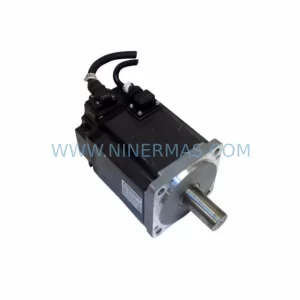
SKU: LSC-060-3-30-560-P5B0H2MM0
LTI Motion LSC-060-3-30-560-P5B0H2MM0 Safety-Reliable Servo Drive
Catalog Continuation
Alternative parts within PLC & Industrial Automation Modules.
Stay inside the same system family when you need substitutes, adjacent modules, or a broader shortlist for procurement review.