Original Industrial Spare Part
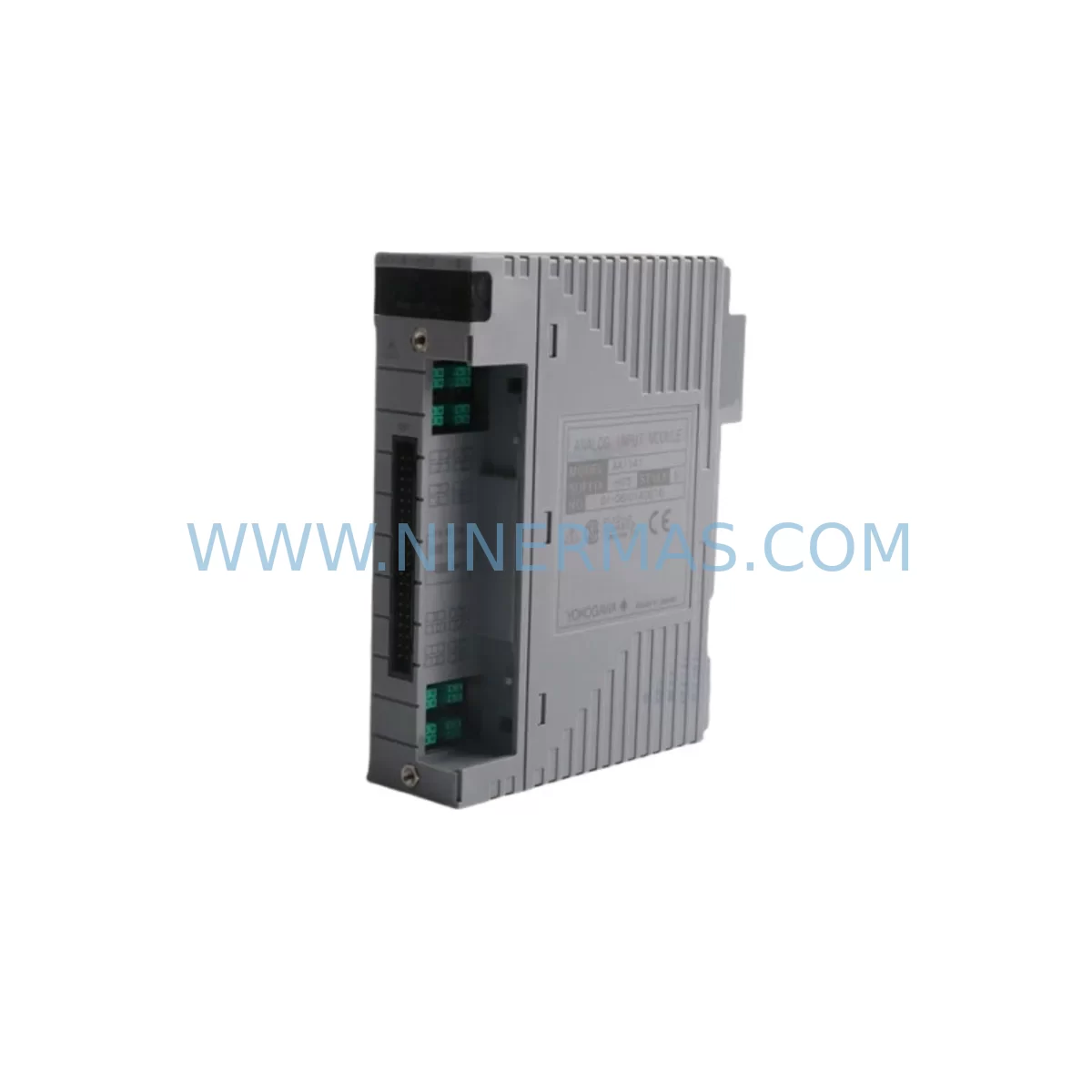
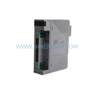
Yokogawa AAP135-S00 Retrofit Pulse Input for Legacy Systems
Verify the part, confirm the platform family, and move straight into quotation with the right commercial details.
RFQ Ready
- SKUAAP135-S00
- CategoryDCS Distributed Control Systems
- BrandYokogawa
- SupportAvailability, lead time, condition, and shipping coordination
How Buyers Usually Use This Page
- Confirm the exact part number and platform family before sending the quote request.
- Use direct email when quantity, condition, and destination are already defined internally.
- Switch to the broader brand or category archive when you need alternates nearby.
Series Navigation
Move through the most common platform families behind this part.
Product RFQ
Send this part directly for quotation.
Include quantity, required condition, destination country, and target delivery timing. Current reference: Yokogawa AAP135-S00 Retrofit Pulse Input for Legacy Systems with SKU AAP135-S00.
Yokogawa AAP135-S00 Retrofit Pulse Input for Legacy Systems
The Yokogawa AAP135-S00 is a pulse input module designed for integration within the CENTUM VP and CS 3000 Distributed Control System (DCS) platforms. As production lines age and original equipment manufacturers discontinue legacy hardware, the AAP135-S00 remains a critical component for facilities that depend on accurate pulse-based signal acquisition in continuous process environments. This module supports direct replacement of discontinued pulse input cards within existing control cabinets, enabling engineering teams to extend the operational life of their automation infrastructure without committing to a full platform migration.
For plants operating CENTUM CS 3000 or transitioning to CENTUM VP, the AAP135-S00 provides a retrofit-compatible solution that preserves existing wiring configurations, backplane slot assignments, and module addressing schemes. Procurement teams managing spare parts lifecycles will find this module essential for maintaining system redundancy and minimizing unplanned downtime in safety-critical applications across oil and gas, petrochemical, power generation, and pharmaceutical sectors.
Upgrade Compatibility Table
| Parameter | AAP135-S00 Specification | Retrofit Consideration |
|---|---|---|
| Module Type | Pulse Input Module | Direct slot-compatible replacement for legacy pulse input cards |
| Platform Compatibility | CENTUM VP / CS 3000 | Verify nest bus version and firmware revision before installation |
| Input Channels | 4 channels (pulse/frequency) | Confirm channel-to-tag mapping in engineering database |
| Signal Range | 0–10 kHz pulse input | Validate field transmitter output frequency against module range |
| Power Consumption | Per Yokogawa specification sheet | Confirm nest power budget before adding module to existing rack |
| Backplane Interface | Nest bus (ESB-11 compatible) | Check nest bus revision; older ESB-11 nests may require firmware update |
| Terminal Wiring | Screw terminal block | Verify terminal block pinout matches existing field cable schedule |
| Module Address | Set via DIP switch / software | Confirm address does not conflict with existing I/O map |
| HMI Compatibility | CENTUM VP HIS / CS 3000 HIS | Update HMI faceplates if tag names or engineering units change |
| Communication Link | V-net / Vnet/IP | Verify network segment and node address assignment |
| Installation Space | Standard CENTUM nest slot | Confirm physical slot availability in existing control cabinet |
| Warranty | 12 Months | Covered from date of shipment; includes pre-shipment functional test |
Retrofit Planning for Existing Automation Systems
Successful integration of the AAP135-S00 into a legacy control system requires a structured pre-installation assessment. Engineers should begin by auditing the existing nest configuration to confirm available slot positions within the field control station (FCS). In many CENTUM CS 3000 installations, the nest bus is managed through the ESB-11 nest bus interface, and any new module insertion must be validated against the current I/O map to prevent address conflicts with co-installed modules such as the AAI143-S00 analog input module or the ADV151-P00 digital input module.
Power budget verification is a mandatory step before physical installation. The nest power supply unit — often an RPS-11 or equivalent redundant power module — must have sufficient headroom to support the AAP135-S00 alongside existing modules including analog output cards such as the AAO145-S00 and digital output modules such as the ADV551-P00. Overloading the nest power supply is a common cause of intermittent faults during retrofit projects and must be ruled out before commissioning.
Terminal wiring adaptation is frequently required when replacing older pulse input cards. Field cable schedules should be cross-referenced against the AAP135-S00 terminal block pinout to confirm signal polarity, shielding requirements, and grounding continuity. In installations where the original wiring was designed for a different module generation, a terminal adapter or marshalling panel modification may be necessary to maintain signal integrity without re-pulling field cables.
Module address configuration must be completed before the module is inserted into the nest. The AAP135-S00 uses a combination of hardware DIP switch settings and software-defined addressing within the CENTUM VP or CS 3000 engineering environment. The system engineer should verify the address assignment in the FCS builder tool and confirm that the corresponding I/O tag definitions in the control database are correctly mapped to the new module’s channel assignments. Any mismatch between the hardware address and the software configuration will result in communication faults that prevent the module from reporting process values to the HMI.
For facilities running CENTUM VP with Vnet/IP communication, the network node address of the FCS hosting the AAP135-S00 must be confirmed against the network topology diagram. In multi-domain systems, the CP451-10 communication processor or equivalent gateway module manages inter-domain data exchange, and any changes to the I/O configuration must be reflected in the domain database to ensure that pulse count data is correctly propagated to supervisory systems and historian platforms.
HMI faceplate updates are often overlooked during retrofit planning. When the AAP135-S00 replaces a module with a different channel count or engineering unit configuration, the corresponding HMI graphics on the CENTUM VP Human Interface Station (HIS) or CS 3000 HIS must be updated to reflect the new tag structure. Failure to update HMI displays can result in operators viewing stale or incorrectly scaled process values during the post-retrofit commissioning period.
All pre-shipment units are functionally tested against Yokogawa factory acceptance criteria before dispatch. Each AAP135-S00 is verified for channel-level pulse counting accuracy, communication link establishment, and module self-diagnostic reporting. This testing protocol reduces the risk of infant mortality failures during field installation and supports the 12-month warranty coverage provided from the date of shipment.
Downtime Control During System Migration
Minimizing control system downtime during an AAP135-S00 retrofit requires careful coordination between the maintenance team, process engineers, and the control system vendor’s field service representative. The recommended approach is to perform the module swap during a planned maintenance window, with the affected process loop placed in manual control mode at the DCS operator station before the physical replacement begins.
Before removing the legacy pulse input module, the engineer should export the current FCS configuration database and create a backup of the control strategy associated with the affected I/O tags. This backup preserves the original program logic — including pulse scaling factors, totalizer reset conditions, and alarm setpoints — and provides a recovery baseline if the new module requires configuration adjustments during commissioning.
The AAP135-S00 supports hot-insertion in CENTUM VP systems with redundant FCS configurations, allowing the module to be installed without powering down the entire nest. However, in non-redundant CS 3000 installations, a controlled nest power cycle may be required to initialize the new module and establish communication with the FCS processor. The maintenance team should confirm the system architecture before attempting hot-insertion to avoid unexpected process interruptions.
Post-installation commissioning should include a channel-by-channel verification of pulse input signals using a calibrated pulse generator or by confirming live process values against an independent measurement reference. The engineer should also verify that the totalizer function blocks in the control strategy are accumulating correctly and that alarm outputs are functioning as expected before returning the loop to automatic control.
Field control continuity is maintained throughout the migration by keeping unaffected I/O modules in service and limiting the scope of each retrofit session to a single module or nest. This incremental approach reduces the risk of cascading faults and allows the operations team to maintain process visibility on the HMI during the replacement procedure.
Retrofit Support FAQ
Q1: Is the AAP135-S00 a direct replacement for the original Yokogawa pulse input module in my CS 3000 system?
A: The AAP135-S00 is designed as a retrofit-compatible replacement for legacy pulse input modules within the CENTUM CS 3000 and CENTUM VP platforms. Before installation, confirm the nest bus revision, module address assignment, and terminal wiring pinout to ensure full compatibility with your existing system configuration.
Q2: What pre-installation checks are required before fitting the AAP135-S00 into an existing nest?
A: Required checks include: nest power budget verification, slot availability confirmation, DIP switch address setting, I/O tag mapping review in the FCS builder, terminal wiring cross-reference, and HMI faceplate update assessment. These steps are documented in the Yokogawa CENTUM VP engineering manual and should be completed before the maintenance window begins.
Q3: Does the AAP135-S00 ship with a functional test certificate?
A: Yes. Each unit undergoes pre-shipment functional testing covering pulse counting accuracy, communication link verification, and module self-diagnostic checks. A test record is available upon request and supports the 12-month warranty coverage provided from the date of shipment.
Q4: What is the lead time and stock availability for the AAP135-S00?
A: The AAP135-S00 is maintained in reserved inventory to support urgent retrofit and emergency replacement requirements. Typical lead times are confirmed at the time of order. For time-critical applications, contact our sales team to discuss priority allocation and long-term supply agreements that align with your spare parts lifecycle plan.
| Product Series | Centum VP |
|---|---|
| Country of Origin | JP |
Catalog Continuation
More Yokogawa modules in the catalog.
Use the brand lane to compare nearby part numbers, platform-adjacent modules, and other inquiry-ready listings before sending your final RFQ.
Catalog Continuation
Alternative parts within DCS Distributed Control Systems.
Stay inside the same system family when you need substitutes, adjacent modules, or a broader shortlist for procurement review.
SKU: PM632 3BSE005831R1
ABB PM632 3BSE005831R1 Retrofit-Compatible Processor for Legacy Systems
SKU: High Performance Communication Controller
Honeywell 51401635-150 Service-Ready Spare for C300