Original Industrial Spare Part
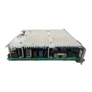
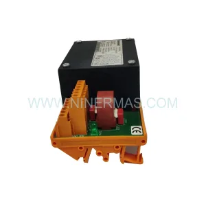
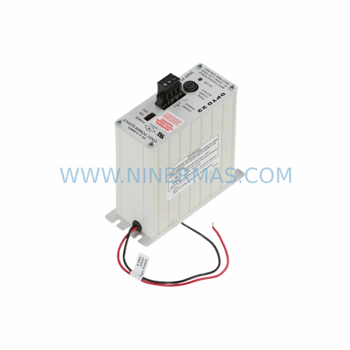
OPTO 22 SNAP-PS5 Retrofit-Compatible Power Supply for Legacy Systems
Verify the part, confirm the platform family, and move straight into quotation with the right commercial details.
RFQ Ready
- SKUSNAP-PS5
- CategoryPLC & Industrial Automation Modules
- BrandOPTO 22
- SupportAvailability, lead time, condition, and shipping coordination
How Buyers Usually Use This Page
- Confirm the exact part number and platform family before sending the quote request.
- Use direct email when quantity, condition, and destination are already defined internally.
- Switch to the broader brand or category archive when you need alternates nearby.
Series Navigation
Move through the most common platform families behind this part.
Product RFQ
Send this part directly for quotation.
Include quantity, required condition, destination country, and target delivery timing. Current reference: OPTO 22 SNAP-PS5 Retrofit-Compatible Power Supply for Legacy Systems with SKU SNAP-PS5.
OPTO 22 SNAP-PS5 Retrofit-Compatible Power Supply for Legacy SNAP Series Systems
The OPTO 22 SNAP-PS5 is a dedicated power supply module engineered for the SNAP Series modular I/O platform — one of the most widely deployed distributed control architectures in process automation, discrete manufacturing, and building management applications. As legacy SNAP racks continue to operate beyond their original design life, the SNAP-PS5 has become a critical retrofit component for engineers tasked with extending system uptime without committing to a full platform migration. NINERMAS maintains verified stock of the SNAP-PS5 to support planned maintenance windows, emergency replacements, and phased modernization programs across global facilities.
When a SNAP-PS5 fails or approaches end-of-service life, the downstream impact is immediate: the entire SNAP rack loses regulated DC power, taking all installed I/O modules — including analog input modules such as the SNAP-AIMA-i, digital output modules such as the SNAP-ODC5, and communication modules such as the SNAP-ETHERNET-M — offline simultaneously. Restoring power quickly and correctly is therefore the highest-priority task in any SNAP system recovery scenario. The SNAP-PS5 slots directly into the dedicated power supply bay of compatible SNAP racks, including the SNAP-B3M and SNAP-B6M mounting racks, without requiring rack modification or firmware changes.
Upgrade Compatibility Table
| Parameter | SNAP-PS5 Specification | Retrofit Notes |
|---|---|---|
| Input Voltage | 85–264 VAC, 47–63 Hz (universal input) | Confirm site supply voltage before installation; no tap adjustment required |
| Output Voltage | +5 VDC regulated | Verify backplane bus voltage with multimeter before powering I/O modules |
| Output Current | 5 A continuous | Calculate total I/O module current draw; do not exceed rated capacity |
| Compatible Racks | SNAP-B3M, SNAP-B6M, SNAP-B10M, SNAP-B16M | Confirm rack model before ordering; power bay form factor is identical across SNAP rack family |
| Communication Module Compatibility | SNAP-ETHERNET-M, SNAP-LCE, SNAP-UP1-ADS | No protocol reconfiguration required after power supply swap |
| Installation Format | Dedicated power bay, tool-free module insertion | No rack drilling or wiring modification required for direct replacement |
| Commissioning Requirement | None for direct replacement | Re-verify I/O module addressing and SNAP PAC controller communication link after power restoration |
| Warranty | 12-Month Warranty — All units shipped by NINERMAS are tested and covered for 12 months from date of delivery | |
Retrofit Planning for Existing Automation Systems
A successful SNAP-PS5 retrofit begins well before the replacement unit arrives on site. Maintenance engineers should first audit the full SNAP rack population — documenting each installed module by slot position, including any SNAP-AIMA-i analog input modules, SNAP-ODC5 digital output modules, SNAP-IAC5 AC input modules, and SNAP-OAC5 AC output modules — to establish a baseline configuration that can be restored immediately after power is re-established. This documentation also serves as the reference for verifying that the SNAP PAC controller, whether a SNAP-PAC-R1 or SNAP-PAC-S1, resumes communication with all I/O modules on the correct network addresses after the power supply swap.
Terminal wiring to the SNAP-PS5 is straightforward: the module accepts line, neutral, and earth ground connections at clearly labeled screw terminals on the front face. Engineers should confirm that the incoming AC feed is isolated at the panel breaker before disconnecting the failed unit, and that the replacement SNAP-PS5 is seated fully into the rack power bay before re-energizing. The backplane connector is keyed to prevent incorrect orientation. After power restoration, the SNAP-ETHERNET-M or other installed communication module will re-establish its Ethernet link to the SNAP PAC controller within seconds, and the controller’s strategy will resume execution from its last saved state without requiring a program download — provided the controller battery is intact and the strategy has not been cleared.
For facilities running mixed SNAP and legacy serial-based control architectures, the SNAP-PS5 replacement is often the first step in a broader modernization that includes migrating serial I/O nodes to Ethernet-based SNAP racks, consolidating multiple small racks onto a single SNAP-B16M rack with a shared SNAP-PS5, and retiring aging SNAP-UP1-ADS serial brain boards in favor of SNAP-ETHERNET-M network adapters. NINERMAS can supply all associated modules — including replacement SNAP-B6M racks, SNAP-ETHERNET-M communication modules, and SNAP-AIMA-i analog input modules — to support a phased rack consolidation without requiring a full PLC platform change.
Downtime Control During System Migration
Minimizing unplanned downtime during a SNAP-PS5 replacement requires a structured approach that protects the existing control program, preserves field wiring integrity, and maintains communication continuity between the SNAP PAC controller and the plant SCADA or HMI system. The recommended procedure is to perform the power supply swap during a scheduled maintenance window rather than under emergency conditions, allowing time to back up the SNAP PAC controller strategy using PAC Control software before de-energizing the rack.
With the strategy backed up and the rack de-energized, the SNAP-PS5 can be removed and replaced in under five minutes. The field wiring to I/O modules remains undisturbed throughout the process, as the power supply module is electrically isolated from the I/O terminal wiring. After the new SNAP-PS5 is installed and the rack is re-energized, engineers should verify that the backplane bus voltage reads within specification, confirm that all I/O modules have re-initialized correctly by checking the SNAP PAC controller’s I/O status display, and validate that the HMI screen — whether a dedicated operator panel or a PC-based SCADA client — is receiving live process data before releasing the system to production.
For sites where even a brief planned outage is operationally difficult, NINERMAS recommends pre-staging a fully tested spare SNAP-PS5 in the control room so that the physical swap can be completed in the shortest possible window. All SNAP-PS5 units supplied by NINERMAS are functionally tested prior to shipment and covered by a 12-month warranty, eliminating the risk of receiving a defective replacement unit that extends the outage beyond the planned window.
Retrofit Support FAQ
Q1: Is the SNAP-PS5 a direct drop-in replacement for the original OPTO 22 power supply in my SNAP rack?
Yes. The SNAP-PS5 is designed as a direct replacement for the standard SNAP Series power supply bay. It uses the same physical form factor, backplane connector, and terminal wiring layout as the original unit. No rack modification, wiring change, or firmware update is required for a direct swap.
Q2: Will my SNAP PAC controller lose its program after the power supply is replaced?
No, provided the SNAP PAC controller — such as a SNAP-PAC-R1 or SNAP-PAC-S1 — has a functional battery and the strategy has not been manually cleared. The controller retains its strategy in non-volatile memory. After the SNAP-PS5 is replaced and the rack is re-energized, the controller will resume strategy execution and re-establish communication with all I/O modules automatically.
Q3: How do I verify that the replacement SNAP-PS5 is functioning correctly after installation?
After installation, measure the backplane bus voltage at the rack test points to confirm it reads within the specified +5 VDC ±5% tolerance. Then check the SNAP PAC controller’s I/O status to confirm all modules have initialized. Verify that the SNAP-ETHERNET-M or other communication module has re-established its network link and that the HMI or SCADA system is receiving live data. NINERMAS performs a functional output test on every SNAP-PS5 unit before shipment.
Q4: What is the warranty coverage and lead time for the SNAP-PS5 from NINERMAS?
All SNAP-PS5 units supplied by NINERMAS are covered by a 12-month warranty from the date of delivery. Units are shipped from verified stock and are available for immediate dispatch to support both planned maintenance and emergency replacement requirements. For current inventory status and lead time confirmation, contact NINERMAS directly.
—
| Product Series | Legacy |
|---|
Catalog Continuation
More OPTO 22 modules in the catalog.
Use the brand lane to compare nearby part numbers, platform-adjacent modules, and other inquiry-ready listings before sending your final RFQ.
Catalog Continuation
Alternative parts within PLC & Industrial Automation Modules.
Stay inside the same system family when you need substitutes, adjacent modules, or a broader shortlist for procurement review.
SKU: SCE906A2-002-01 SCE906A200201
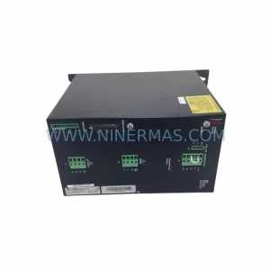
Pacific Scientific SCE906A2-002-01 Retrofit Servo Amplifier
SKU: EPC500 3183062451
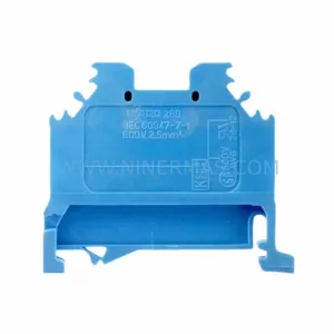
Alfa Laval EPC500 3183062451 Service-Ready Spare Part