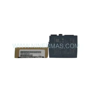
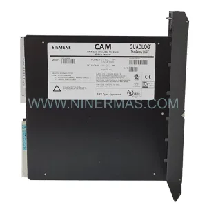
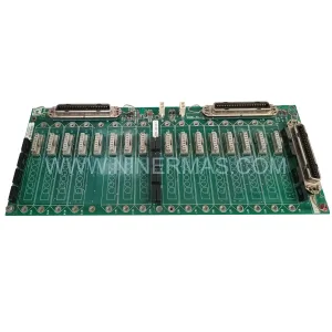
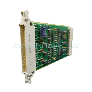
Original Industrial Spare Part
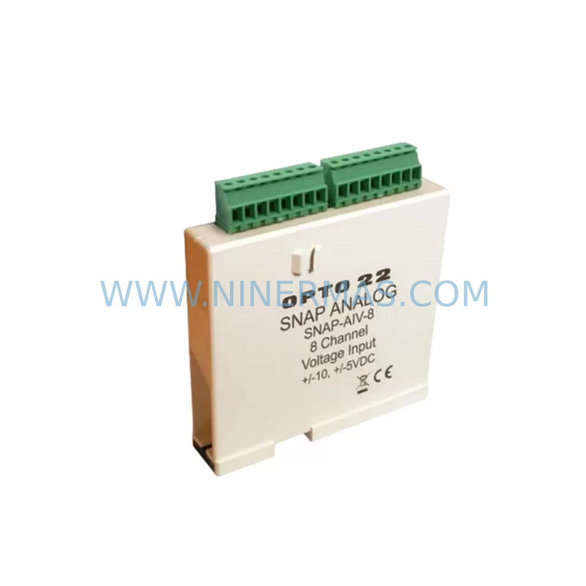
OPTO 22 SNAP-AIV-8 Service-Ready Spare Part
Verify the part, confirm the platform family, and move straight into quotation with the right commercial details.
RFQ Ready
- SKUSNAP-AIV-8
- CategoryPLC & Industrial Automation Modules
- BrandOPTO 22
- SupportAvailability, lead time, condition, and shipping coordination
How Buyers Usually Use This Page
- Confirm the exact part number and platform family before sending the quote request.
- Use direct email when quantity, condition, and destination are already defined internally.
- Switch to the broader brand or category archive when you need alternates nearby.
Series Navigation
Move through the most common platform families behind this part.
Product RFQ
Send this part directly for quotation.
Include quantity, required condition, destination country, and target delivery timing. Current reference: OPTO 22 SNAP-AIV-8 Service-Ready Spare Part with SKU SNAP-AIV-8.
OPTO 22 SNAP-AIV-8 Service-Ready Spare Part for Industrial Maintenance
The OPTO 22 SNAP-AIV-8 is an 8-channel analog voltage input module designed for the SNAP Ethernet-based I/O platform. Built to accept ±10 VDC analog signals, it delivers high-resolution signal acquisition for process monitoring, feedback control, and safety interlock verification across demanding industrial environments. For maintenance engineers managing aging SNAP PAC systems, the SNAP-AIV-8 represents a critical spare — one whose failure can immediately interrupt analog signal chains, compromise PID loop integrity, and trigger unplanned shutdowns in continuous production facilities.
Whether you are conducting a scheduled annual overhaul, responding to an emergency fault isolation event, or building a strategic spare parts inventory for a multi-year maintenance contract, the SNAP-AIV-8 must be sourced as an original, tested component. Counterfeit or refurbished analog input modules introduce calibration drift, signal offset errors, and intermittent channel failures that are notoriously difficult to diagnose under live plant conditions. NINERMAS supplies only original OPTO 22 SNAP-AIV-8 units, each pre-shipment tested and backed by a 12-month warranty.
Spare Maintenance Table
| Parameter | Specification |
|---|---|
| Model | SNAP-AIV-8 |
| Brand | OPTO 22 |
| Series | SNAP PAC I/O |
| Module Type | 8-Channel Analog Voltage Input |
| Input Range | ±10 VDC |
| Resolution | 16-bit |
| Channels | 8 (single-ended) |
| Communication | SNAP PAC Brain / Rack backplane |
| Operating Temperature | 0°C to 70°C |
| Mounting | SNAP I/O Rack (4-position or 16-position) |
| Compatibility | SNAP PAC R-series, S-series brains; SNAP-LCM4 controllers |
| Safety Relevance | Analog feedback for interlock and PID control loops |
| Origin | USA |
| Condition | Original, New |
| Pre-Shipment Test | Yes — channel-by-channel signal verification |
| Warranty | 12 Months |
Maintenance Planning for Continuous Operation
When a SNAP-AIV-8 module is flagged for replacement during a control cabinet inspection or fault isolation routine, experienced maintenance engineers know that the module itself is rarely the only component requiring attention. A thorough site assessment should extend to the surrounding system architecture to prevent repeat failures and reduce the risk of secondary downtime.
Begin by inspecting the SNAP PAC rack (such as the SNAP-B16PR or SNAP-B4D) for backplane connector wear, corrosion, or mechanical damage that may have contributed to signal degradation on the analog channels. The SNAP-LCM4 local controller module or the associated SNAP-ENET-RTC brain should be checked for firmware currency and communication health — a failing brain can misreport analog values and mask the true source of a process alarm.
On the signal side, verify the integrity of field wiring terminations at the SNAP-AIPM signal conditioning module or any inline signal isolators used to protect the analog inputs from ground loops and common-mode noise. In high-EMI environments such as variable frequency drive (VFD) panels or motor control centers, unshielded or improperly grounded signal cables are a frequent cause of analog channel drift that is incorrectly attributed to module failure.
Power supply stability is equally critical. The SNAP-PS5 or SNAP-PS24 power supply module feeding the I/O rack should be load-tested and inspected for output ripple, particularly in facilities where the power distribution system is shared with heavy motor loads. An unstable rack supply voltage will cause erratic analog readings across all channels of the SNAP-AIV-8, even when the module itself is fully functional.
For systems integrating the SNAP-AIV-8 into safety interlock loops, cross-reference the analog input values against the SNAP-AOV-25 analog output module or the associated SNAP-IDC5 digital input module used for interlock confirmation. Discrepancies between expected and actual signal states during commissioning of a replacement module are a reliable indicator of upstream wiring or configuration issues that must be resolved before returning the system to service.
Procurement engineers building a strategic spare parts list for SNAP PAC systems should also consider stocking the SNAP-AIV-4 (4-channel analog input) as a complementary spare for lower-density I/O racks, and the SNAP-ENET2 dual-port Ethernet brain for systems where network redundancy is a maintenance priority. Maintaining a minimum of one SNAP-AIV-8 per critical control cabinet significantly reduces mean time to repair (MTTR) during unplanned outages.
Site Replacement Workflow
Replacing a SNAP-AIV-8 in a live industrial facility requires a structured approach to minimize control system disruption and ensure signal integrity is fully restored before the process is returned to automatic mode.
Step 1 — Isolation and Documentation: Place the affected control loop in manual mode at the DCS or SCADA level. Document the current analog channel configuration, engineering unit scaling, and any offset or gain corrections applied in the SNAP PAC controller software (PAC Control or PAC Manager). Photograph the existing wiring terminations before disconnection.
Step 2 — Module Removal: De-energize the I/O rack supply using the dedicated rack power isolator. Remove the SNAP-AIV-8 by releasing the module latch and sliding it clear of the backplane connector. Inspect the backplane pins for damage or contamination before installing the replacement unit.
Step 3 — Replacement Installation: Insert the new OPTO 22 SNAP-AIV-8 into the same rack slot. Re-energize the rack and confirm the module is recognized by the brain or controller. Reconnect field wiring per the documented termination layout, ensuring correct shielding and grounding practices are maintained.
Step 4 — Verification and Recommissioning: Using PAC Manager or the SNAP PAC controller’s diagnostic interface, verify that all 8 analog channels are reading within expected engineering unit ranges. Apply a known reference signal to each channel if a signal generator is available. Confirm PID loop setpoints and interlock thresholds are correctly configured before returning the loop to automatic control.
Step 5 — Documentation Update: Record the replacement in the site maintenance management system (CMMS), update the spare parts inventory, and flag the next scheduled inspection interval for the replaced module’s rack position.
Spare Parts Support FAQ
Q1: Is the SNAP-AIV-8 supplied by NINERMAS an original OPTO 22 product?
Yes. NINERMAS supplies only original OPTO 22 SNAP-AIV-8 modules sourced through verified industrial supply channels. Each unit undergoes pre-shipment functional testing with channel-by-channel signal verification before dispatch. A 12-month warranty is provided on all units.
Q2: What SNAP PAC systems is the SNAP-AIV-8 compatible with?
The SNAP-AIV-8 is compatible with all standard SNAP PAC I/O racks, including 4-position and 16-position rack configurations. It operates with SNAP PAC R-series and S-series brains, as well as SNAP-LCM4 local controller modules. Compatibility with legacy SNAP Ultimate I/O systems should be verified against the specific brain firmware version in use.
Q3: Can NINERMAS support long-term supply of the SNAP-AIV-8 for multi-year maintenance contracts?
Yes. NINERMAS maintains ongoing stock of high-demand SNAP PAC spare parts including the SNAP-AIV-8. For facilities requiring guaranteed supply under a long-term maintenance agreement, we recommend contacting our sales team to discuss reserved stock arrangements and volume pricing. Contact: sale@ninermas.com | +0086 187 5021 5667.
Q4: What should I check if the replacement SNAP-AIV-8 shows unexpected analog readings after installation?
First verify that field wiring shielding and grounding are correctly implemented — ungrounded shields are the most common cause of post-replacement signal noise. Next, confirm that the engineering unit scaling in PAC Manager matches the field transmitter output range. Check the rack power supply output voltage under load, and inspect the backplane connector for contamination. If issues persist, contact NINERMAS technical support for remote diagnostic assistance.
| Product Series | Other series |
|---|
Catalog Continuation
More OPTO 22 modules in the catalog.
Use the brand lane to compare nearby part numbers, platform-adjacent modules, and other inquiry-ready listings before sending your final RFQ.
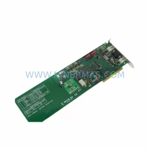
Catalog Continuation
Alternative parts within PLC & Industrial Automation Modules.
Stay inside the same system family when you need substitutes, adjacent modules, or a broader shortlist for procurement review.
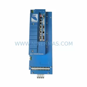
SKU: MMC-SD-12.0-460-D
KOLLMORGEN MMC-SD-12.0-460-D Retrofit-Compatible Servo Drive
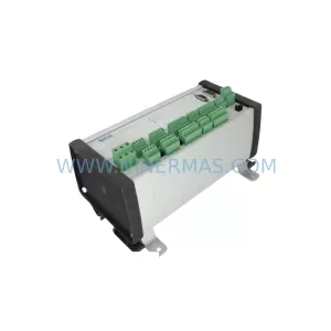
SKU: BM-DP12 1070075887-202
Bosch BM-DP12 1070075887-202 Retrofit-Compatible PROFIBUS DP Module