Original Industrial Spare Part
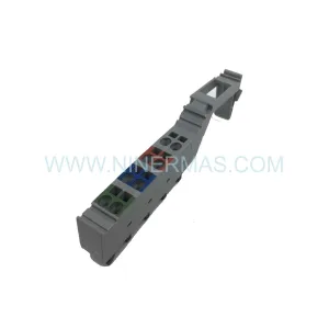
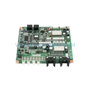
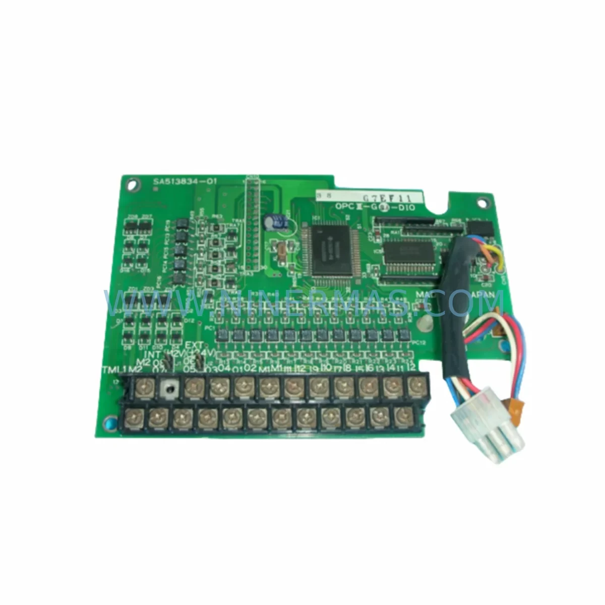
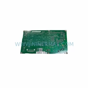
FUJI SA513834-01 Retrofit-Compatible Control Board for Legacy Systems
Verify the part, confirm the platform family, and move straight into quotation with the right commercial details.
RFQ Ready
- SKUSA513834-01
- CategoryPLC & Industrial Automation Modules
- BrandFUJI
- SupportAvailability, lead time, condition, and shipping coordination
How Buyers Usually Use This Page
- Confirm the exact part number and platform family before sending the quote request.
- Use direct email when quantity, condition, and destination are already defined internally.
- Switch to the broader brand or category archive when you need alternates nearby.
Series Navigation
Move through the most common platform families behind this part.
Product RFQ
Send this part directly for quotation.
Include quantity, required condition, destination country, and target delivery timing. Current reference: FUJI SA513834-01 Retrofit-Compatible Control Board for Legacy Systems with SKU SA513834-01.
FUJI SA513834-01 Retrofit-Compatible Control Board for Legacy Systems
The FUJI SA513834-01 is a retrofit-compatible control board engineered to support smooth migration from end-of-life FUJI automation platforms to modernized control architectures. As legacy FUJI inverter and drive systems approach their end-of-support lifecycle, plant engineers and maintenance teams face increasing pressure to source reliable replacement boards that maintain backward compatibility with existing wiring, terminal layouts, and control logic. The SA513834-01 addresses this challenge directly — offering a verified drop-in replacement path that minimizes engineering rework, reduces commissioning time, and protects the integrity of existing automation programs.
Whether you are managing a planned upgrade during a scheduled maintenance window or responding to an unplanned board failure on a critical production line, the SA513834-01 provides the electrical and mechanical compatibility required to restore system operation with confidence. NINERMAS maintains ready stock of this board with full pre-shipment functional testing, ensuring that every unit dispatched has been verified against FUJI’s original performance specifications before leaving our facility.
Upgrade Compatibility Table
| Parameter | Details |
|---|---|
| Part Number | SA513834-01 |
| Brand | FUJI Electric |
| Function | Control Board / PCB Assembly |
| Compatible Series | FUJI FRENIC Series (FRENIC-Multi, FRENIC-Ace, FRENIC-MEGA) |
| Interface Compatibility | Compatible with existing terminal block wiring and backplane connector layout |
| Communication Support | RS-485 / Modbus RTU (subject to host drive model) |
| Installation Requirement | Direct board swap; verify drive frame size and mounting rail clearance before installation |
| Replacement Recommendation | Suitable as direct replacement for failed or degraded SA513834-01 boards in FUJI FRENIC drives |
| Commissioning Notes | Re-initialize parameter settings after board swap; verify I/O signal mapping and analog reference levels |
| Pre-Shipment Testing | Full functional test performed on every unit prior to dispatch |
| Warranty | 12 Months from date of shipment |
| Origin | Japan |
| Availability | In Stock — Ready to Ship |
Retrofit Planning for Existing Automation Systems
Successful retrofit of the SA513834-01 into an existing FUJI drive system requires careful pre-installation planning across several dimensions. Before removing the failed board, maintenance engineers should document the current parameter set stored in the drive — particularly acceleration/deceleration ramp times, frequency reference source selection, motor nameplate data, and any PID control loop configurations. Many FUJI FRENIC drives support parameter upload via the keypad or an optional PC loader cable, which allows the full parameter set to be saved and restored after the board replacement is complete.
Terminal wiring compatibility is a primary concern during any control board retrofit. The SA513834-01 interfaces with the drive’s main control terminal block, which typically carries analog input signals (0–10V or 4–20mA frequency reference), digital input commands (forward run, reverse run, multi-step speed selection), relay output contacts, and the RS-485 communication port used for Modbus RTU integration with upstream SCADA or PLC systems. Engineers should verify that all terminal assignments match the original wiring diagram before powering the drive after board replacement.
In systems where the FUJI FRENIC drive communicates with a Siemens S7-300 PLC or an Omron CJ-series controller via Modbus RTU, the communication node address and baud rate settings stored on the original board must be re-entered on the replacement SA513834-01 to restore network connectivity without requiring changes to the PLC program. Similarly, where the drive is integrated into a control cabinet alongside FUJI FRENIC option cards — such as the OPC-G1-RY relay output card or the OPC-G1-SI serial interface card — the option card slot assignments and communication parameters must be verified post-swap.
For plants running FUJI FRENIC drives in multi-drive configurations with a shared DC bus or common braking resistor, the SA513834-01 replacement should be followed by a full system power-up sequence test to confirm that the regenerative braking logic and DC bus voltage monitoring functions are operating correctly. Where the drive controls a motor connected to a gearbox or conveyor system, a no-load test run at reduced speed is recommended before returning the axis to full production speed.
In control cabinets where space is constrained, engineers should also confirm that the replacement board’s connector orientation and ribbon cable routing do not create mechanical interference with adjacent components such as the FUJI FRENIC keypad extension cable, the drive’s EMC filter module, or any third-party signal isolator modules mounted on DIN rail within the same enclosure. Where the original installation used a FUJI BU-series braking unit or an external reactor for harmonic suppression, these components remain unaffected by the control board swap and do not require reconfiguration.
Downtime Control During System Migration
Minimizing production downtime during a control board replacement is a primary operational objective for any plant maintenance team. The SA513834-01 retrofit process is designed to support rapid board exchange with the following recommended sequence to protect program logic and maintain field control continuity.
Prior to initiating the board swap, the maintenance team should place the drive in a safe stop state, isolate the drive from the AC supply using the upstream circuit breaker or disconnect switch, and discharge the DC bus capacitors according to FUJI’s published lockout/tagout procedure. The parameter backup step — using the drive keypad or a FUJI Loader PC tool connected via the RS-232C or USB programming cable — should be completed before the board is removed. This backup protects against parameter loss in the event that the replacement board ships with factory default settings.
Once the SA513834-01 is installed and the drive is powered up, the parameter restore sequence should be executed before any run command is issued. Following parameter restore, the engineer should verify the following in sequence: motor rotation direction at low speed (5–10 Hz), analog input signal levels at the control terminal block, digital input response to external command signals, relay output contact operation, and Modbus communication link status with the upstream controller. This structured commissioning sequence typically allows a trained engineer to complete the full board swap and recommission the drive within two to four hours, keeping unplanned downtime to a minimum.
For critical production lines where even brief downtime carries significant cost, NINERMAS recommends maintaining a spare SA513834-01 board in the plant’s on-site spare parts inventory. Our 12-month warranty covers all boards supplied, and our team can provide advance replacement units to support planned maintenance schedules or emergency breakdown response.
Retrofit Support FAQ
Q1: Is the SA513834-01 a direct replacement for the original FUJI board, or does it require wiring modifications?
The SA513834-01 is designed as a direct replacement for the original board in compatible FUJI FRENIC drive models. In most cases, no wiring modifications are required at the control terminal block. Engineers should verify the terminal assignment diagram against the original wiring documentation before installation to confirm compatibility with their specific drive variant.
Q2: What pre-shipment testing is performed on each SA513834-01 unit?
Every SA513834-01 unit supplied by NINERMAS undergoes full functional testing prior to dispatch. This includes power-on verification, signal path continuity checks, and communication interface validation. A test report is available upon request. All units are covered by a 12-month warranty from the date of shipment.
Q3: Can the SA513834-01 be used in a drive that communicates via Modbus RTU with an upstream PLC?
Yes. The SA513834-01 supports RS-485 / Modbus RTU communication in compatible FUJI FRENIC drive configurations. After board replacement, the Modbus node address, baud rate, and parity settings must be re-entered to match the original configuration. No changes to the upstream PLC program are required if the communication parameters are correctly restored.
Q4: What is the lead time and stock availability for the SA513834-01?
NINERMAS maintains in-stock inventory of the SA513834-01 to support both planned maintenance and emergency breakdown requirements. Standard orders are dispatched within 1–3 business days. For volume procurement or long-term spare parts programs with fixed lead times, please contact our sales team to discuss stock commitment arrangements.
| Product Series | Legacy |
|---|
Catalog Continuation
More FUJI modules in the catalog.
Use the brand lane to compare nearby part numbers, platform-adjacent modules, and other inquiry-ready listings before sending your final RFQ.
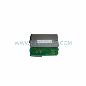
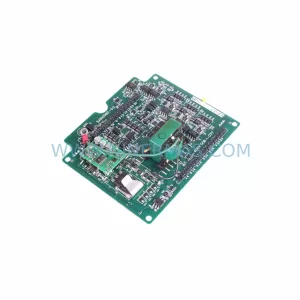
SKU: G11-PPCB-4-1.5 SA528530-06
FUJI SA528530-06 Safety-Reliable Control Board for Critical Control Sites
Catalog Continuation
Alternative parts within PLC & Industrial Automation Modules.
Stay inside the same system family when you need substitutes, adjacent modules, or a broader shortlist for procurement review.
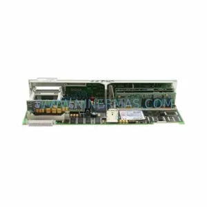
SKU: 6FC5357-0BB12-0AE0
Siemens 6FC5357-0BB12-0AE0 Service-Ready Industrial Spare Part
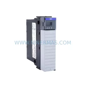
SKU: 3BSE011790R1(PXHK401)
ABB 3BSE011790R1 PXHK401 Retrofit-Ready Communication Module