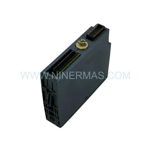
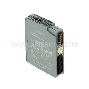
Original Industrial Spare Part
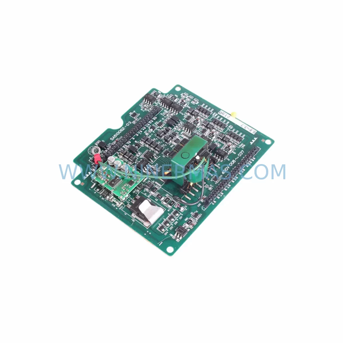
FUJI SA510062-02 Retrofit-Compatible I/O Module for Legacy Systems
Verify the part, confirm the platform family, and move straight into quotation with the right commercial details.
RFQ Ready
- SKUSA510062-02
- CategoryPLC & Industrial Automation Modules
- BrandFUJI
- SupportAvailability, lead time, condition, and shipping coordination
How Buyers Usually Use This Page
- Confirm the exact part number and platform family before sending the quote request.
- Use direct email when quantity, condition, and destination are already defined internally.
- Switch to the broader brand or category archive when you need alternates nearby.
Series Navigation
Move through the most common platform families behind this part.
Product RFQ
Send this part directly for quotation.
Include quantity, required condition, destination country, and target delivery timing. Current reference: FUJI SA510062-02 Retrofit-Compatible I/O Module for Legacy Systems with SKU SA510062-02.
FUJI SA510062-02 Retrofit-Compatible I/O Module: Seamless Legacy System Upgrade
The FUJI SA510062-02 is a retrofit-compatible I/O module engineered to serve as a direct replacement for discontinued FUJI series control system components. Designed for engineers and maintenance teams managing aging automation infrastructure, this module supports smooth migration from end-of-life hardware without requiring full system redesign. Whether you are restoring a failed control cabinet, extending the operational life of a legacy PLC rack, or executing a phased modernization program, the SA510062-02 delivers the compatibility and reliability your application demands.
FUJI’s industrial automation platforms — including the MICREX-SX, MICREX-F, and NP series — have been widely deployed across manufacturing, power distribution, and process control environments for decades. As original hardware reaches end-of-life, sourcing verified replacement modules becomes critical to maintaining uptime. The SA510062-02 addresses this need directly, offering a tested, warranted, and immediately available solution for facilities that cannot afford extended downtime or full system replacement.
Upgrade Compatibility Table
| Parameter | Details |
|---|---|
| Part Number | SA510062-02 |
| Brand | FUJI Electric |
| Series Compatibility | FUJI MICREX-SX / MICREX-F / NP Series |
| Module Type | I/O Module (Digital / Analog — confirm with datasheet) |
| Backplane Interface | Compatible with FUJI standard rack backplane connectors |
| Installation Format | DIN rail / rack-mount (verify slot pitch against existing chassis) |
| Communication Compatibility | Compatible with FUJI proprietary bus; verify protocol version with host CPU module |
| Terminal Wiring | Screw-terminal block; verify wire gauge and torque spec before reconnection |
| Power Requirement | Supplied via backplane; confirm rack power budget before installation |
| Replacement Recommendation | Direct swap for SA510062-02 original; confirm firmware revision compatibility |
| Commissioning Note | Re-assign module address in CPU configuration after slot insertion |
| Warranty | 12 Months — covers manufacturing defects from date of shipment |
| Pre-Shipment Testing | Yes — functional test performed before dispatch |
| Stock Status | Available — contact for lead time confirmation |
Retrofit Planning for Existing Automation Systems
Integrating the SA510062-02 into an existing FUJI control system requires a structured pre-installation review. Begin by auditing the host rack or chassis — FUJI modular racks such as the NP1 series backplane must have sufficient available slots and confirmed power headroom before adding or replacing I/O modules. The rack’s power supply module (e.g., FUJI NP1PS series) should be checked against the aggregate current draw of all installed modules, including the SA510062-02, to prevent undervoltage conditions that can corrupt program execution.
Terminal wiring is a common source of commissioning delays. Before removing the failed module, photograph or document all field wiring connections. The SA510062-02 uses a screw-terminal interface; verify wire gauge compatibility and re-torque all terminals to specification after reconnection. If the original installation used a removable terminal block, confirm that the connector pinout matches the replacement module before powering up.
Module address assignment is the next critical step. FUJI CPU modules — such as the NP1L-RS1 or NP1L-ET1 communication modules — reference I/O modules by slot address. After physically installing the SA510062-02, open the system configuration in FUJI’s SX-Programmer or equivalent programming tool and verify that the slot assignment matches the original configuration. Failure to confirm this step can result in I/O mapping errors that affect HMI screen data, alarm logic, and interlock sequences.
For systems that include FUJI HMI panels — such as the V9 series or UG series operator terminals — verify that the tag database and screen data reference the correct I/O addresses after module replacement. If the original module failure caused a communication fault, the HMI may retain a cached alarm state that requires manual reset after the new module is confirmed online.
Communication link integrity should be verified end-to-end. If the SA510062-02 is part of a distributed I/O network using FUJI’s T-Link or FL-net protocol, confirm that the network scan cycle and node address settings are correctly restored. In systems where a FUJI NP1L-RS4 serial communication module or NP1L-ET1 Ethernet module manages upstream SCADA connectivity, verify that the I/O data map exported to the host system reflects the updated module configuration.
For larger retrofit projects involving multiple I/O modules, signal isolators, and analog input cards, it is advisable to stage the replacement in sections — replacing one module at a time and verifying field signals before proceeding to the next. This approach minimizes the risk of introducing multiple fault points simultaneously and allows the maintenance team to confirm each I/O channel individually before returning the system to automatic operation.
Downtime Control During System Migration
Minimizing production downtime during a FUJI I/O module replacement requires preparation before the maintenance window begins. The most effective approach is to back up the complete CPU program — including all data registers, retentive memory, and communication parameters — using FUJI SX-Programmer or the applicable loader software. Store the backup on an isolated engineering laptop and verify the file integrity before proceeding with any hardware changes.
Where possible, pre-configure the SA510062-02 module address and verify its slot assignment in an offline simulation environment before the physical swap. This allows the engineering team to identify any configuration conflicts — such as duplicate module addresses or mismatched I/O point counts — without consuming time during the live maintenance window.
During the physical replacement, isolate the affected I/O section using the system’s safety interlock or manual bypass procedures. If the control system supports partial rack hot-swap (verify with FUJI documentation for your specific CPU and rack model), the replacement can be performed without a full system shutdown. For systems that require a cold restart, coordinate with production scheduling to align the maintenance window with a planned production break.
After module installation and address confirmation, perform a controlled power-up sequence: energize the rack, confirm the CPU transitions to RUN mode without fault codes, and verify each I/O channel against the field device checklist before releasing the system to automatic control. Document the replacement in the site maintenance log, including the module serial number, installation date, and post-commissioning test results. This record supports future warranty claims and provides traceability for regulatory compliance audits.
Retrofit Support FAQ
Q1: Is the SA510062-02 a direct drop-in replacement for the original FUJI module?
The SA510062-02 is designed as a form-fit-function replacement for the original FUJI part of the same number. Before installation, confirm the firmware revision of your host CPU module is compatible with the replacement I/O module. In most cases, no program changes are required; however, a slot address verification in the CPU configuration is always recommended after any module swap.
Q2: What commissioning steps are required after installation?
After physically installing the module, verify the slot address assignment in your FUJI programming software, confirm all terminal wiring connections are secure and correctly torqued, and perform a channel-by-channel I/O verification against your field device list. If the system includes an HMI, confirm that all affected screen tags are reading correctly and that no residual fault alarms remain active.
Q3: Has the module been tested before shipment?
Yes. Every SA510062-02 unit undergoes a functional pre-shipment test to verify basic I/O operation and communication interface integrity before dispatch. A 12-month warranty covering manufacturing defects is included from the date of shipment. Warranty claims should be submitted with the original invoice and a description of the observed fault.
Q4: What is the stock availability and lead time?
The SA510062-02 is held in inventory and is available for prompt dispatch. Lead times vary by destination and shipping method. Contact our sales team at sale@ninermas.com or +0086 187 5021 5667 to confirm current stock levels and arrange shipment. For urgent requirements, expedited dispatch options are available.
| Product Series | Legacy |
|---|
Catalog Continuation
More FUJI modules in the catalog.
Use the brand lane to compare nearby part numbers, platform-adjacent modules, and other inquiry-ready listings before sending your final RFQ.
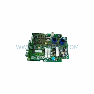
SKU: G11-PPCB-4-1.5 SA528530-06
FUJI SA528530-06 Safety-Reliable Control Board for Critical Control Sites
Catalog Continuation
Alternative parts within PLC & Industrial Automation Modules.
Stay inside the same system family when you need substitutes, adjacent modules, or a broader shortlist for procurement review.
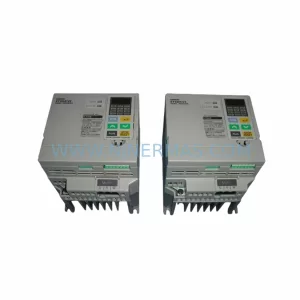
SKU: 3G3EV-AB007M-E
OMRON 3G3EV-AB007M-E Retrofit-Compatible VFD for Legacy Systems
SKU: 2711P-RDT15C SER B
Allen-Bradley 2711P-RDT15C SER B Industrial Spare Part