Original Industrial Spare Part
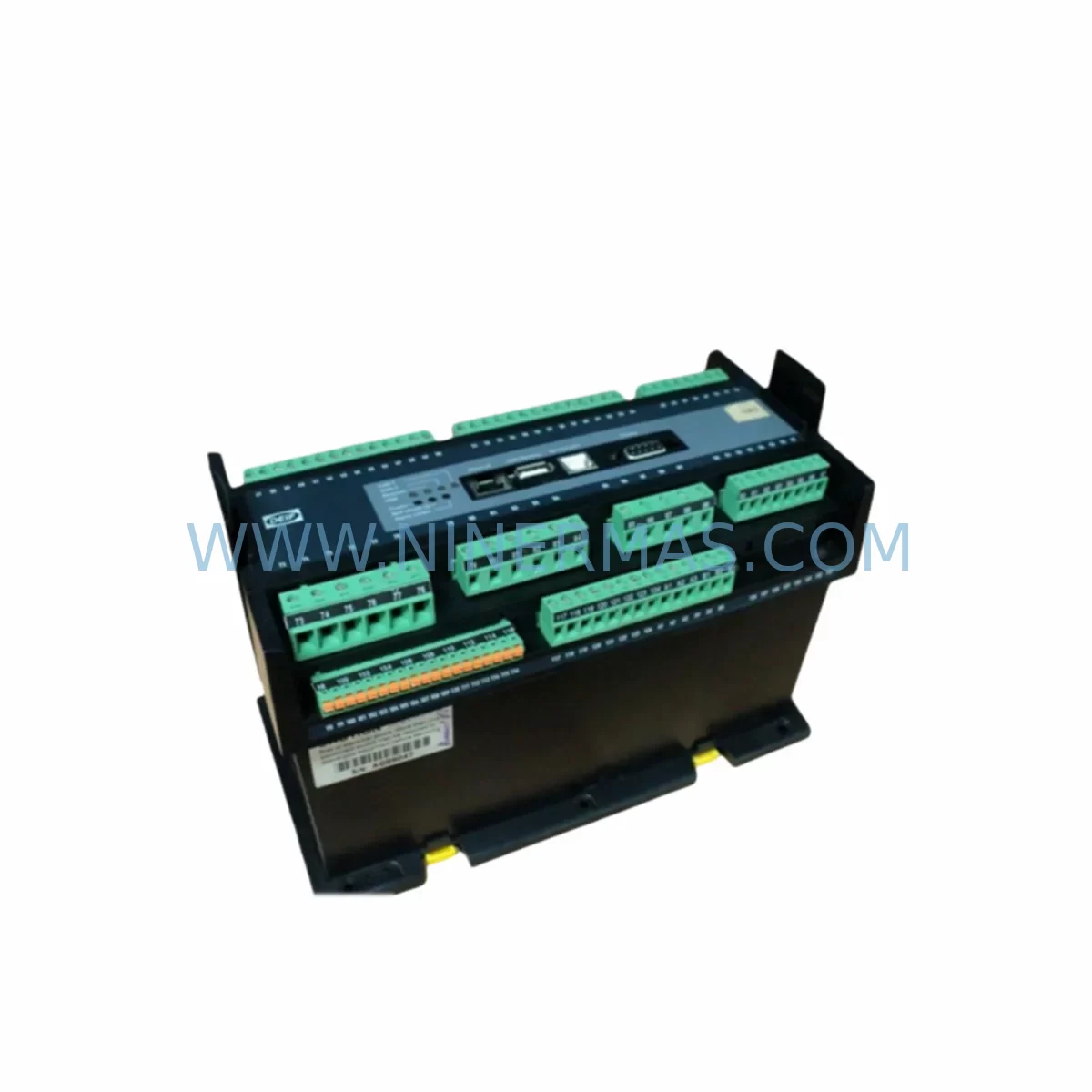
DEIF AGC/GS/3 AGC Retrofit-Compatible Genset Controller
Verify the part, confirm the platform family, and move straight into quotation with the right commercial details.
RFQ Ready
- SKUAGC/GS/3 AGC
- CategoryPLC & Industrial Automation Modules
- BrandDEIF
- SupportAvailability, lead time, condition, and shipping coordination
How Buyers Usually Use This Page
- Confirm the exact part number and platform family before sending the quote request.
- Use direct email when quantity, condition, and destination are already defined internally.
- Switch to the broader brand or category archive when you need alternates nearby.
Series Navigation
Move through the most common platform families behind this part.
Product RFQ
Send this part directly for quotation.
Include quantity, required condition, destination country, and target delivery timing. Current reference: DEIF AGC/GS/3 AGC Retrofit-Compatible Genset Controller with SKU AGC/GS/3 AGC.
DEIF AGC/GS/3 AGC Retrofit-Compatible Genset Controller: Legacy AGC Series Upgrade & Smooth Migration
The DEIF AGC/GS/3 AGC is a retrofit-ready automatic genset controller designed to serve as a direct functional replacement for legacy DEIF AGC series units deployed in standby power systems, parallel generator sets, and industrial backup installations. As original AGC series hardware reaches end-of-life and spare parts become increasingly scarce, the AGC/GS/3 AGC provides a validated migration path that preserves existing panel wiring, minimises downtime, and extends the operational life of your control infrastructure by years.
Engineered for compatibility with DEIF’s established AGC platform architecture, this unit supports the same terminal layout conventions and communication interfaces familiar to engineers who have worked with the AGC 4, AGC 200, and AGC 245 controller families. Whether you are replacing a failed unit in an emergency or executing a planned fleet upgrade across multiple generator sets, the AGC/GS/3 AGC is stocked and pre-shipment tested to reduce commissioning risk on site.
Upgrade Compatibility Table
| Parameter | Legacy AGC Series | DEIF AGC/GS/3 AGC | Retrofit Notes |
|---|---|---|---|
| Mounting Format | Panel-mount, DIN cutout | Panel-mount, DIN cutout | Verify exact cutout dimensions before installation |
| Supply Voltage | 8–36 V DC | 8–36 V DC | Confirm DC bus capacity; check existing PSU output |
| Terminal Wiring | Screw-terminal block | Screw-terminal block | Map legacy terminal numbers to new terminal layout before rewiring |
| Communication Interface | RS-485 / Modbus RTU | RS-485 / Modbus RTU | Verify baud rate and slave address settings match SCADA or HMI configuration |
| I/O Configuration | Analogue + Digital I/O | Analogue + Digital I/O | Confirm I/O count; expand via DEIF MSC-3 I/O expansion module if required |
| Programming Tool | DEIF PC Utility Software | DEIF PC Utility Software | Use USB programming cable; back up existing parameter file before upload |
| Backplane / Rack | Standalone panel unit | Standalone panel unit | No backplane dependency; confirm panel depth clearance ≥ 60 mm |
| HMI Compatibility | DEIF LM-3 / external HMI | DEIF LM-3 / external HMI | Retain existing HMI screens; verify Modbus register map alignment |
| Warranty | OEM warranty expired | 12-Month Warranty | Covered from date of shipment; pre-shipment tested |
| Availability | Discontinued / scarce | In stock, ready to ship | Contact for lead time confirmation on bulk orders |
Retrofit Planning for Existing Automation Systems
A successful AGC/GS/3 AGC retrofit begins well before the unit arrives on site. Engineers should start by auditing the existing control cabinet to confirm available panel space, DC supply rail capacity, and the condition of existing terminal wiring. In many legacy installations, the 24 V DC supply is shared between the genset controller, protection relays, and auxiliary I/O modules — verifying that the existing power supply unit can sustain the combined load of the replacement controller and any new expansion hardware is a critical first step.
Terminal mapping is the next priority. Legacy AGC series wiring diagrams should be cross-referenced against the AGC/GS/3 AGC terminal layout to identify any pin-for-pin differences in analogue inputs (speed pickup, voltage sensing, current transformer inputs), digital inputs (remote start, mains failure, emergency stop), and relay outputs (fuel solenoid, starter motor, alarm). Where the terminal count or function assignment differs, a wiring adapter harness or revised terminal block labelling should be prepared in advance to avoid errors during the live changeover window.
Communication continuity is equally important. If the legacy controller was integrated into a SCADA system or building management platform via Modbus RTU over RS-485, the replacement unit must be configured with the same slave address, baud rate, parity, and stop bits before the cutover. The DEIF LM-3 local display module, if present in the panel, should also be verified for register map compatibility so that existing HMI screens continue to display generator status, load values, and alarm states without requiring a full screen redraw.
For sites running parallel generator sets, the synchronisation and load-sharing configuration stored in the original AGC unit must be exported using the DEIF PC Utility Software and a compatible USB programming cable before the old unit is removed. This parameter file — covering droop settings, load ramp rates, dead-bus detection thresholds, and inter-controller communication addresses — forms the baseline for the replacement unit’s commissioning. Where the original parameter file is unavailable, engineers should plan additional commissioning time to rebuild the configuration from the site’s original design documentation.
I/O expansion requirements should also be assessed at this stage. Sites that have grown beyond the original I/O count of the legacy controller may benefit from adding a DEIF MSC-3 expansion module or a dedicated digital input/output relay card to the panel. Signal isolators may be required where analogue sensor wiring runs exceed recommended cable lengths or where ground loop interference has been identified as a historical issue. In some installations, a DEIF PPM-3 power protection module or a dedicated voltage and frequency monitoring relay is installed alongside the genset controller to provide independent protection — these devices should be checked for compatibility with the replacement unit’s relay output assignments.
Finally, confirm that the physical installation space accommodates the AGC/GS/3 AGC’s depth behind the panel fascia. Older control cabinets with dense wiring harnesses may require cable management adjustments to achieve the minimum rear clearance. Where the original unit was secured with a panel-mount locking frame, verify that the same frame dimensions apply or source a compatible replacement bezel.
Downtime Control During System Migration
Minimising generator downtime during an AGC controller replacement requires a structured pre-outage preparation process. The most effective approach is to complete all parameter backup, terminal mapping, and communication configuration work during normal operation — so that when the maintenance window opens, the physical swap and recommissioning can be completed within a single shift.
Before removing the legacy unit, confirm that the generator set is in manual mode and that any automatic start signals from the mains failure detection circuit or remote SCADA system have been inhibited. This prevents an unintended start command from reaching the engine during the wiring changeover. Where the site operates a duty/standby generator arrangement, the standby unit should be confirmed as available and capable of carrying the full site load before the duty generator’s controller is taken offline.
During the physical installation, work methodically through the terminal map, connecting one functional group at a time — power supply first, then protection inputs, then control outputs, then communication wiring. Label each terminal as it is connected and photograph the completed wiring before applying power. This documentation supports fault-finding if any issue arises during initial power-up and provides a reference for future maintenance teams.
After power-up, load the backed-up parameter file via the USB programming cable and verify all analogue input readings against known reference values — engine speed, oil pressure, coolant temperature, and AC voltage and frequency — before attempting a test start. Confirm that all relay output assignments are correct by stepping through the controller’s I/O test mode. Once the test start is completed successfully and the generator is confirmed to be running within normal parameters, the communication link to the SCADA or HMI system should be re-established and all alarm and status registers verified.
The entire process — from panel opening to generator return to automatic mode — can typically be completed within four to six hours for a single genset installation when preparation has been thorough. For parallel generator sets or sites with complex load-sharing configurations, allow additional time for synchronisation verification and load transfer testing. All units supplied by NINERMAS are pre-shipment tested to confirm basic functionality before despatch, reducing the risk of a commissioning delay caused by a unit fault.
Retrofit Support FAQ
Q1: Is the DEIF AGC/GS/3 AGC a direct drop-in replacement for my existing AGC series controller?
The AGC/GS/3 AGC is functionally compatible with the AGC series platform and shares the same panel-mount format and communication interfaces. However, terminal-for-terminal wiring compatibility depends on the specific legacy variant installed. We recommend cross-referencing the existing wiring diagram against the AGC/GS/3 AGC terminal layout before installation. Our technical team can assist with terminal mapping if you provide the original unit’s model number and wiring diagram.
Q2: Can I transfer my existing parameter file to the replacement unit?
Yes. Parameter files created with the DEIF PC Utility Software can be uploaded to the AGC/GS/3 AGC using a compatible USB programming cable. Back up the existing parameter file from the legacy unit before removal. If the original file is unavailable, the replacement unit will need to be configured from scratch using the site’s design documentation. Contact our support team for guidance on parameter reconstruction.
Q3: What communication protocols does the AGC/GS/3 AGC support, and will it work with my existing SCADA system?
The AGC/GS/3 AGC supports RS-485 Modbus RTU communication, which is the standard protocol used across the AGC series platform. Provided your SCADA or HMI system is configured to communicate via Modbus RTU and the slave address, baud rate, and register map are correctly matched, the replacement unit will integrate with your existing monitoring infrastructure without requiring changes to the SCADA software.
Q4: Does the unit come with a warranty, and has it been tested before shipment?
Yes. All DEIF AGC/GS/3 AGC units supplied by NINERMAS carry a 12-month warranty from the date of shipment. Each unit undergoes pre-shipment functional testing to verify power-up, I/O response, and communication interface operation before despatch. In the unlikely event of a unit fault within the warranty period, contact our after-sales team at sale@ninermas.com for return and replacement support.
| Product Series | Other series |
|---|
Catalog Continuation
More DEIF modules in the catalog.
Use the brand lane to compare nearby part numbers, platform-adjacent modules, and other inquiry-ready listings before sending your final RFQ.
Catalog Continuation
Alternative parts within PLC & Industrial Automation Modules.
Stay inside the same system family when you need substitutes, adjacent modules, or a broader shortlist for procurement review.
SKU: 14L41-RS0B0-B24R-ST5S00N-R0SU
LENZE 14L41-RS0B0-B24R-ST5S00N-R0SU Retrofit for Legacy Systems
SKU: CI540 3BSE001077R1
ABB CI540 3BSE001077R1 Spare Part for Industrial Maintenance
SKU: ZINT-541 3AUA00000658960
ABB ZINT-541 3AUA00000658960 Retrofit-Compatible Inverter Power Module