Original Industrial Spare Part
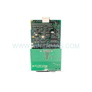
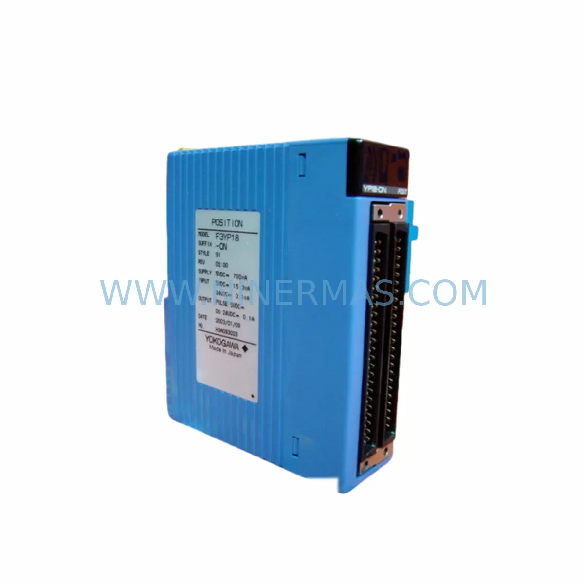
Yokogawa F3YD32-1A Retrofit Digital Output for Legacy Systems
Verify the part, confirm the platform family, and move straight into quotation with the right commercial details.
RFQ Ready
- SKUF3YD32-1A
- CategoryDCS Distributed Control Systems
- BrandYokogawa
- SupportAvailability, lead time, condition, and shipping coordination
How Buyers Usually Use This Page
- Confirm the exact part number and platform family before sending the quote request.
- Use direct email when quantity, condition, and destination are already defined internally.
- Switch to the broader brand or category archive when you need alternates nearby.
Series Navigation
Move through the most common platform families behind this part.
Product RFQ
Send this part directly for quotation.
Include quantity, required condition, destination country, and target delivery timing. Current reference: Yokogawa F3YD32-1A Retrofit Digital Output for Legacy Systems with SKU F3YD32-1A.
Yokogawa F3YD32-1A Retrofit Digital Output for Legacy Systems
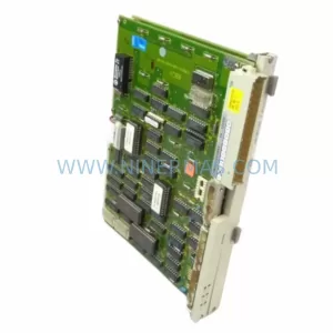
The Yokogawa F3YD32-1A is a 32-point transistor digital output module designed for the FA-M3 Range Free Multi-Controller platform. As legacy FA-M3 installations continue to operate across process industries, power generation, and discrete manufacturing, the F3YD32-1A remains a critical component for maintaining output control integrity in aging control cabinets. Whether you are replacing a failed unit, extending the operational life of an end-of-life system, or executing a phased modernization of your automation infrastructure, the F3YD32-1A provides a direct, retrofit-compatible solution that minimizes engineering rework and reduces unplanned downtime.
NINERMAS maintains verified stock of the F3YD32-1A sourced from authorized supply channels, with each unit subject to pre-shipment functional testing and covered by a 12-month warranty. Our inventory is specifically maintained to support maintenance teams managing legacy Yokogawa FA-M3 systems where original spare parts are no longer available through standard distribution.
Upgrade Compatibility Table
| Parameter | F3YD32-1A Specification | Retrofit Consideration |
|---|---|---|
| Output Points | 32-point transistor output | Verify field wiring terminal count matches existing I/O assignment |
| Output Type | Transistor (NPN/PNP depending on variant) | Confirm sink/source logic matches existing field devices |
| Backplane Interface | FA-M3 standard bus connector | Compatible with F3BU13-0N and F3BU06-0N base units |
| Slot Addressing | Slot-based module addressing via CPU scan | Confirm slot number and I/O address map in existing ladder program |
| Power Consumption | Supplied via backplane 5 VDC bus | Verify F3PW01-0S power supply capacity before adding modules |
| Communication Compatibility | FA-M3 internal bus; no standalone protocol | No protocol migration required; CPU handles all bus communication |
| Installation Space | Single-slot FA-M3 module form factor | Confirm available slot in existing base unit before ordering |
| Program Compatibility | Fully compatible with existing FA-M3 ladder/function block programs | No program modification required for direct replacement |
| HMI Screen Impact | Output tag addresses remain unchanged | No HMI screen revision required if slot address is preserved |
| Warranty | 12-Month Warranty | Covered from date of shipment; includes functional test certification |
Retrofit Planning for Existing Automation Systems
Successful replacement of the F3YD32-1A within an operating FA-M3 system requires a structured pre-installation review. Before removing the failed module, maintenance engineers should document the current slot assignment and cross-reference the I/O address map in the CPU program. The FA-M3 platform — built around controllers such as the F3PU20-0S and F3PU16-0S — uses slot-based addressing, meaning that inserting the replacement module into the correct physical slot is essential to restoring the original output tag mapping without any program modification.
The base unit configuration must also be confirmed prior to installation. FA-M3 base units such as the F3BU13-0N (13-slot) and F3BU06-0N (6-slot) define the physical rack into which all I/O and communication modules are installed. If the base unit itself shows signs of wear — particularly the backplane bus connectors — this should be addressed during the same maintenance window to avoid repeat failures after the F3YD32-1A is restored to service.
Power budget verification is a frequently overlooked step in FA-M3 retrofit projects. The F3PW01-0S power supply module provides the 5 VDC backplane bus that feeds all installed modules. When adding or replacing modules, engineers should confirm that the total current draw of all installed modules — including digital input modules such as the F3XD32-3A and F3XD64-3N, analog modules such as the F3AD08-0S and F3DA04-6R, and communication modules such as the F3NC11-0N and F3LC11-1N — does not exceed the rated output of the installed power supply. Exceeding the power budget is a common root cause of intermittent module faults in aging FA-M3 cabinets.
For systems that include a mix of digital output modules — for example, where the F3YD32-1A handles 32-point low-density output zones alongside a higher-density F3YD64-1P module managing 64-point output groups — the replacement plan should account for the full output module inventory in the rack. This ensures that the maintenance team can prioritize which modules are most critical to continued production and sequence the replacement work accordingly.
Terminal wiring adaptation is another key consideration. The F3YD32-1A uses a standard FA-M3 terminal connector. Before reinstalling the replacement module, inspect the field wiring harness for insulation degradation, loose ferrules, or corroded terminals — particularly in high-humidity or high-vibration environments. Rewiring errors at this stage are a leading cause of commissioning delays after module replacement.
Downtime Control During System Migration
Minimizing production downtime during F3YD32-1A replacement requires advance preparation and a clear handover protocol between the maintenance team and the process control operator. The following approach is recommended for sites where the affected output module controls active field devices:
First, place the affected output zone in a safe state using the existing CPU program’s forced output or inhibit function before physically removing the module. This prevents uncontrolled output transitions during the hot-swap or cold-swap procedure. The FA-M3 CPU — whether an F3PU20-0S or a legacy F3PU16-0S — supports forced I/O operations through the programming tool, allowing the maintenance team to freeze output states before module removal.
Second, back up the current CPU program to a laptop or programming device using Yokogawa’s WideField3 engineering software before beginning any hardware work. This ensures that the original ladder logic, function block diagrams, and I/O address assignments are preserved and can be restored immediately if any unexpected issue arises during the replacement procedure.
Third, after installing the F3YD32-1A replacement and reconnecting the field wiring, perform a point-by-point output verification test before returning the system to automatic mode. This involves forcing each output point individually from the programming tool and confirming the corresponding field device response. This step typically adds 15–30 minutes to the maintenance window but significantly reduces the risk of post-commissioning faults caused by wiring errors or address mismatches.
For sites with redundant control architectures or where the FA-M3 system operates in parallel with a newer DCS or PLC platform, coordinate the replacement window with the broader control system team to ensure that any cross-system interlocks or communication links — including those managed by F3NC11-0N or F3LC11-1N communication modules — remain active throughout the maintenance period.
Retrofit Support FAQ
Q: Is the F3YD32-1A a direct replacement for the original module without any program changes?
A: Yes. The F3YD32-1A is a direct slot-compatible replacement for the original module within the FA-M3 platform. Provided the replacement module is installed in the same physical slot, no changes to the CPU program, HMI screens, or I/O address assignments are required. The CPU will recognize the module automatically on the next power cycle or hot-insertion scan.
Q: What pre-shipment testing is performed on the F3YD32-1A?
A: Each F3YD32-1A unit supplied by NINERMAS undergoes functional output verification testing prior to shipment. Test results are available upon request. All units are shipped with a 12-month warranty covering manufacturing defects and functional failures under normal operating conditions.
Q: How do I confirm terminal wiring compatibility before installation?
A: The F3YD32-1A uses the standard FA-M3 40-pin terminal connector. Cross-reference the existing field wiring diagram against the F3YD32-1A terminal assignment table in the Yokogawa FA-M3 I/O Module User’s Manual (IM 34M06Q11-01E). If the original wiring harness is intact and correctly labeled, no rewiring should be required for a direct replacement.
Q: What is the lead time and stock availability for the F3YD32-1A?
A: NINERMAS maintains ready stock of the F3YD32-1A to support urgent maintenance requirements. Standard lead time for in-stock units is 3–7 business days for international shipment. For large-quantity orders or long-term supply agreements covering multiple FA-M3 spare parts, please contact our sales team directly to discuss inventory reservation and pricing.
| Product Series | FA-M3 |
|---|---|
| Country of Origin | JP |
Catalog Continuation
More Yokogawa modules in the catalog.
Use the brand lane to compare nearby part numbers, platform-adjacent modules, and other inquiry-ready listings before sending your final RFQ.
Catalog Continuation
Alternative parts within DCS Distributed Control Systems.
Stay inside the same system family when you need substitutes, adjacent modules, or a broader shortlist for procurement review.