Original Industrial Spare Part
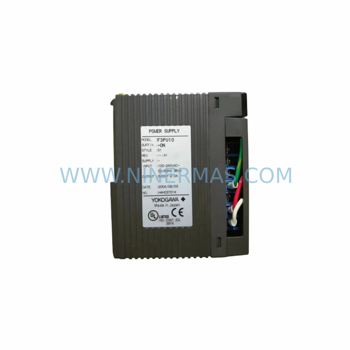
YOKOGAWA F3PU10-0N Retrofit-Compatible Power Supply for Legacy Systems
Verify the part, confirm the platform family, and move straight into quotation with the right commercial details.
RFQ Ready
- SKUF3PU10-ON F3PU10-0N
- CategoryDCS Distributed Control Systems
- BrandYokogawa
- SupportAvailability, lead time, condition, and shipping coordination
How Buyers Usually Use This Page
- Confirm the exact part number and platform family before sending the quote request.
- Use direct email when quantity, condition, and destination are already defined internally.
- Switch to the broader brand or category archive when you need alternates nearby.
Series Navigation
Move through the most common platform families behind this part.
Product RFQ
Send this part directly for quotation.
Include quantity, required condition, destination country, and target delivery timing. Current reference: YOKOGAWA F3PU10-0N Retrofit-Compatible Power Supply for Legacy Systems with SKU F3PU10-ON F3PU10-0N.
YOKOGAWA F3PU10-0N Retrofit-Compatible Power Supply for Legacy Systems
The YOKOGAWA F3PU10-0N is a ruggedized power supply module engineered for the FA-M3 series programmable controller platform — one of YOKOGAWA’s most widely deployed industrial automation architectures across process manufacturing, utilities, and heavy industry. As the FA-M3 platform matures and original procurement channels tighten, the F3PU10-0N has become a critical retrofit component for engineers tasked with sustaining legacy control systems, extending operational life, and executing controlled migrations without full system replacement.
Whether you are replacing a failed unit on an active production line, building a spare parts inventory ahead of a planned shutdown, or executing a phased upgrade of an aging control cabinet, the F3PU10-0N provides the electrical foundation that every FA-M3 rack depends on. This module supplies regulated DC power to all installed I/O and communication modules within the base unit, and its compatibility with both older and current FA-M3 rack configurations makes it an indispensable component in retrofit planning.
Before installing a replacement F3PU10-0N, engineers should verify the total power consumption of all modules installed in the rack — including analog input modules such as the F3AD04-1N or F3AD08-1N, digital output modules such as the F3YD32-3N, and any communication modules such as the F3LC11-1N Ethernet interface or F3LP02-0N PROFIBUS-DP module. Exceeding the rated output capacity of the power supply is a common cause of intermittent faults and unexpected CPU resets during retrofit commissioning. Confirm that the aggregate load across all slots does not exceed the F3PU10-0N’s rated output before energizing the rack.
Terminal wiring compatibility is another key checkpoint. The F3PU10-0N accepts standard AC input within the rated voltage range and provides isolated DC bus output to the backplane. When replacing an older power supply in a legacy cabinet, inspect the existing wiring harness for insulation degradation, verify that the input fusing matches the module’s inrush current profile, and confirm that the cabinet’s grounding arrangement meets YOKOGAWA’s installation guidelines. Improper grounding is a frequent source of noise-induced faults in retrofitted FA-M3 systems, particularly in environments with variable-frequency drives or high-current switching equipment nearby.
Backplane interface alignment is straightforward for direct F3PU10-0N-to-F3PU10-0N replacements, as the module occupies the dedicated power supply slot on all standard FA-M3 base units including the F3BU04-0N, F3BU06-0N, and F3BU16-0N racks. However, if the retrofit involves migrating from an earlier power supply variant, confirm that the backplane connector pinout and mechanical retention mechanism are compatible before committing to the replacement. Physical fitment issues discovered during a live shutdown window significantly increase unplanned downtime risk.
Program logic and CPU compatibility are not directly affected by a power supply replacement, but engineers should take the opportunity during any planned outage to verify that the FA-M3 CPU module — such as the F3SP71-4N or F3SP76-7N — retains its program memory and configuration data after power cycling. Battery-backed RAM modules should be inspected and replaced if the battery voltage is marginal, as a power supply swap is an ideal time to address latent memory retention risks without scheduling an additional maintenance window.
HMI continuity is a practical concern during FA-M3 power supply retrofits. If the control system communicates with a YOKOGAWA ProSafe-RS safety controller, a CENTUM VP DCS, or a third-party HMI via the F3LC11-1N or a serial communication module such as the F3LE01-5T, confirm that the communication link is re-established and all screen tags are updating correctly after the replacement module is energized. Communication timeouts during the restart sequence can trigger alarm floods that complicate post-retrofit verification.
Installation space confirmation is essential in densely populated control cabinets. The F3PU10-0N occupies a fixed slot width consistent with the FA-M3 modular form factor, but cable routing, adjacent module clearances, and ventilation requirements should be assessed before the maintenance window begins. Pre-staging the replacement module, pre-cutting any required cable extensions, and preparing a commissioning checklist in advance are proven practices for minimizing total downtime during field replacement.
Upgrade Compatibility Table
| Parameter | Details |
|---|---|
| SKU / Part Number | F3PU10-0N |
| Brand / Manufacturer | YOKOGAWA |
| Series | FA-M3 Programmable Controller |
| Module Type | Power Supply Module |
| Compatible Racks | F3BU04-0N, F3BU06-0N, F3BU16-0N and standard FA-M3 base units |
| Compatible CPUs | F3SP71-4N, F3SP76-7N and FA-M3 series CPU modules |
| Backplane Interface | FA-M3 standard power supply slot (dedicated, non-I/O slot) |
| Communication Compatibility | Supports all FA-M3 communication modules (F3LC11-1N, F3LP02-0N, F3LE01-5T, etc.) |
| Replacement Suitability | Direct drop-in replacement for failed or end-of-life F3PU10-0N units |
| Installation Requirement | Verify total rack load; inspect input wiring and grounding before energizing |
| Commissioning Focus | Power-on self-test, CPU program retention, HMI tag verification, comms link check |
| Origin | Japan |
| Warranty | 12-Month Warranty — all units tested before shipment |
Retrofit Planning for Existing Automation Systems
A successful FA-M3 power supply retrofit begins well before the maintenance window opens. The F3PU10-0N sits at the center of a broader ecosystem of modules that must all function correctly after the replacement is complete. Start by auditing the full rack population: document every installed module by slot position, including analog input modules, digital I/O modules, pulse input modules, and any special function modules. Calculate the total current draw and confirm it falls within the F3PU10-0N’s rated output capacity with adequate margin for thermal derating in high-ambient-temperature environments.
Communication modules deserve particular attention during retrofit planning. If the FA-M3 system uses an F3LC11-1N Ethernet interface module for SCADA connectivity, or an F3LP02-0N PROFIBUS-DP module for field device integration, confirm that these modules resume normal communication after the power supply is replaced and the rack completes its initialization sequence. Some communication modules require a brief warm-up period before establishing stable links, and this should be accounted for in the post-retrofit verification checklist.
For systems that include signal isolation between field instruments and FA-M3 analog input modules, verify that any external signal isolators or loop-powered transmitters connected to modules such as the F3AD04-1N are not affected by the momentary power interruption during the swap. In critical process applications, coordinating the power supply replacement with a planned process hold or safe state is strongly recommended.
If the retrofit is part of a broader control cabinet upgrade that also involves replacing the FA-M3 CPU module or expanding the I/O count by adding additional base units, the F3PU10-0N replacement should be sequenced as the first step, ensuring stable power delivery before any other module changes are made. Programming cable connections using a YOKOGAWA-compatible programming tool should be verified after the replacement to confirm that the CPU is accessible for any required program updates or parameter adjustments.
Downtime Control During System Migration
Minimizing downtime during an FA-M3 power supply replacement requires disciplined pre-planning and a structured execution sequence. Before the maintenance window begins, back up the complete CPU program — including all ladder logic, function block diagrams, and system parameters — to a laptop running the YOKOGAWA WideField3 programming environment. Confirm that the backup is readable and complete before proceeding. This step protects against the unlikely but consequential scenario of program loss during the power cycle.
During the replacement, work methodically: de-energize the rack, remove the failed F3PU10-0N, inspect the power supply slot and backplane connector for contamination or physical damage, install the replacement module, and re-energize in a controlled sequence. Avoid rushing the energization step — allow the module to complete its internal self-test before evaluating system status indicators.
After power is restored, verify CPU status, confirm that all I/O modules are recognized by the CPU, check communication link status on all installed communication modules, and validate HMI screen data against known process values. Document the replacement with a timestamped maintenance record including the old module’s serial number, the replacement module’s serial number, and the post-replacement verification results. This record supports future maintenance planning and warranty tracking.
For facilities managing multiple FA-M3 systems across a plant, maintaining a small buffer stock of F3PU10-0N modules significantly reduces mean time to repair when unplanned failures occur. Given the module’s role as the single power source for the entire rack, a failed power supply renders all installed I/O and communication modules non-functional until the replacement is complete. Proactive inventory management is the most effective downtime control strategy available.
Retrofit Support FAQ
Q: Is the F3PU10-0N a direct replacement for all FA-M3 power supply variants?
A: The F3PU10-0N is compatible with standard FA-M3 base units including the F3BU04-0N, F3BU06-0N, and F3BU16-0N racks. If your existing installation uses an earlier or variant power supply model, verify the backplane connector type and rated output specifications before ordering. Our team can assist with compatibility confirmation based on your existing module’s nameplate data.
Q: Will replacing the power supply affect the CPU program or retain memory?
A: In most FA-M3 configurations, program memory is retained in battery-backed RAM within the CPU module and is not affected by a power supply replacement. However, we recommend backing up the full program before any maintenance activity and inspecting the CPU battery condition during the same maintenance window.
Q: What pre-shipment testing is performed on replacement F3PU10-0N modules?
A: All F3PU10-0N units supplied by NINERMAS are functionally tested prior to shipment, including output voltage verification under load and insulation resistance checks. Each unit is covered by a 12-month warranty from the date of shipment. Test records are available upon request.
Q: What is the typical lead time and stock availability for the F3PU10-0N?
A: NINERMAS maintains inventory of the F3PU10-0N to support urgent replacement requirements. Standard orders are processed and shipped promptly. Contact our sales team at sale@ninermas.com or +0086 187 5021 5667 to confirm current stock levels and lead time for your specific quantity requirement.
| Product Series | FA-M3 |
|---|---|
| Country of Origin | JP |
Catalog Continuation
More Yokogawa modules in the catalog.
Use the brand lane to compare nearby part numbers, platform-adjacent modules, and other inquiry-ready listings before sending your final RFQ.
Catalog Continuation
Alternative parts within DCS Distributed Control Systems.
Stay inside the same system family when you need substitutes, adjacent modules, or a broader shortlist for procurement review.
SKU: High Performance Communication Controller
Honeywell 51401635-150 Service-Ready Spare for C300
SKU: 6DD2920-0AR2 6DD2920-OAR2
Siemens 6DD2920-0AR2 Service-Ready Spare Part for Industrial Maintenance