Original Industrial Spare Part
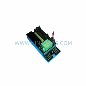
Yokogawa F3CR04-ON Service-Ready Spare Part for Industrial Maintenance
Verify the part, confirm the platform family, and move straight into quotation with the right commercial details.
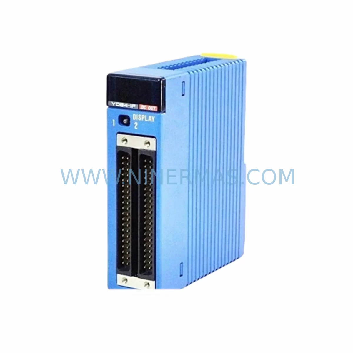
RFQ Ready
- SKUF3CR04-ON
- CategoryDCS Distributed Control Systems
- BrandYokogawa
- SupportAvailability, lead time, condition, and shipping coordination
How Buyers Usually Use This Page
- Confirm the exact part number and platform family before sending the quote request.
- Use direct email when quantity, condition, and destination are already defined internally.
- Switch to the broader brand or category archive when you need alternates nearby.
Series Navigation
Move through the most common platform families behind this part.
Product RFQ
Send this part directly for quotation.
Include quantity, required condition, destination country, and target delivery timing. Current reference: Yokogawa F3CR04-ON Service-Ready Spare Part for Industrial Maintenance with SKU F3CR04-ON.
Yokogawa F3CR04-ON Service-Ready Spare Part for Industrial Maintenance
The Yokogawa F3CR04-ON is a contact relay output module designed for the FA-M3 Series Programmable Logic Controller (PLC) platform — one of Yokogawa’s most widely deployed process and factory automation architectures. As a service-ready spare part, the F3CR04-ON is stocked and tested to support rapid field replacement, minimise unplanned downtime, and sustain continuous production in manufacturing, petrochemical, power generation, and infrastructure environments where system availability is non-negotiable.
Sourced as an original Yokogawa component, this module is verified against factory specifications before shipment. Each unit is covered by a 12-month warranty and dispatched with full pre-shipment functional testing, giving maintenance engineers and procurement teams confidence in both quality and lead-time reliability.
Spare Maintenance Table
| Parameter | Specification / Detail |
|---|---|
| SKU / Part Number | F3CR04-ON |
| Brand | Yokogawa Electric Corporation |
| Series | FA-M3 (Wide Series PLC) |
| Module Type | Contact Relay Output Module |
| Output Points | 4 points (relay contact) |
| Output Type | Normally Open (NO) relay contact |
| Rated Load Voltage | AC 250 V / DC 30 V |
| Rated Load Current | 2 A per point |
| Isolation Method | Relay (mechanical isolation) |
| Compatibility | FA-M3 base units: F3BU04-0N, F3BU08-0N, F3BU16-0N, F3BU32-0N and expansion bases |
| Installation | Slide-in module, DIN-rail mounted base unit |
| Operating Temperature | 0 °C to 55 °C |
| Operating Humidity | 10% to 90% RH (non-condensing) |
| Origin | Japan |
| Warranty | 12 Months from shipment date |
| Condition | Original, new / service-ready tested |
| Pre-shipment Test | Functional output verification performed |
| Maintenance Recommendation | Replace relay output modules every 5–7 years or upon contact wear indication; inspect wiring terminals and fuse holders at each scheduled PM cycle |
Maintenance Planning for Continuous Operation
When a relay output module such as the F3CR04-ON is flagged for replacement during a scheduled preventive maintenance (PM) cycle or an emergency fault isolation, experienced maintenance engineers know that the module itself is rarely the only component requiring attention. A thorough site inspection should extend to the surrounding electrical circuit and control cabinet infrastructure to prevent repeat failures and ensure a clean return to service.
Begin by inspecting the FA-M3 power supply module (such as the F3PU20-0N or F3PU40-0N) that feeds the base unit. Voltage sag or ripple at the backplane can accelerate relay contact wear and cause intermittent output faults that are misdiagnosed as module failure. Verify DC bus voltage under load before inserting the replacement F3CR04-ON.
Next, examine the FA-M3 CPU module (F3SP22-0S, F3SP28-3N, F3SP38-6N, or equivalent) for firmware currency and diagnostic error logs. Output module faults are often recorded in the CPU’s self-diagnostic buffer; clearing these logs and confirming the CPU’s I/O map is correctly configured for the replacement slot is a mandatory step before re-energising the system.
The terminal block wiring connected to the F3CR04-ON output points deserves close inspection. Relay output modules driving inductive loads — motor contactors, solenoid valves, or control relays — generate back-EMF transients that degrade terminal insulation over time. Replace any discoloured or brittle ferrule-terminated wires and confirm that surge suppressors or RC snubber circuits are fitted across inductive loads to protect the new relay contacts.
If the FA-M3 rack includes digital input modules (F3XD08-1N, F3XD16-1N) monitoring the same field devices controlled by the F3CR04-ON outputs, verify that input signal levels and common reference voltages are within specification. A shared field wiring fault can simultaneously stress both input and output modules.
For systems integrating FA-M3 analogue output modules (F3YA04-1N or similar) alongside relay outputs in the same control loop — for example, in PID-controlled heating or flow applications — confirm that the analogue signal reference and the relay switching circuit share a clean common ground. Ground loops introduced during maintenance are a frequent source of post-repair instability.
Communication infrastructure should not be overlooked. If the FA-M3 rack communicates via an F3LE01-5T Ethernet module or an F3LC11-1F PROFIBUS-DP module, confirm that the network link is stable and that the SCADA or DCS host has not flagged the slot as faulted. Some host systems latch I/O fault alarms that must be manually cleared after a module swap.
Finally, review the fuse holders and miniature circuit breakers (MCBs) protecting the output field circuits. Relay contact failure under overload conditions frequently blows the associated field fuse; replacing the F3CR04-ON without replacing a blown fuse will result in an immediate apparent re-failure. Maintain a stock of appropriately rated fuses (typically 2 A fast-blow for relay output circuits) alongside your F3CR04-ON spare.
Procurement engineers should consider establishing a long-term supply agreement for the F3CR04-ON and associated FA-M3 modules. As the FA-M3 platform matures, original module availability from distribution channels becomes less predictable. Securing a committed stock of 2–4 units per installed rack, reviewed annually, is a proven strategy for lifecycle risk management in legacy automation systems.
Site Replacement Workflow
Step 1 — Isolation & Safety: Follow site LOTO (Lockout/Tagout) procedures. De-energise the FA-M3 base unit or the specific output field circuit. Confirm zero-energy state with a calibrated voltage tester before touching the module or terminal wiring.
Step 2 — Document Current Configuration: Record the slot position, wiring labels, and any module DIP-switch or jumper settings on the outgoing F3CR04-ON. Photograph the terminal block before disconnecting wires. Retrieve the CPU’s I/O assignment table to confirm the replacement module will occupy the identical logical address.
Step 3 — Remove Faulty Module: Loosen the module retaining screw, slide the F3CR04-ON out of the base unit slot, and place it in an anti-static bag for failure analysis or return-to-vendor processing.
Step 4 — Inspect Slot & Backplane Connector: Visually inspect the base unit backplane connector for bent pins, corrosion, or contamination. Clean with approved contact cleaner if necessary. A damaged backplane connector on the base unit (F3BU series) will cause the replacement module to fault immediately — address this before insertion.
Step 5 — Insert Replacement F3CR04-ON: Align the module with the slot guide rails and slide firmly until the backplane connector is fully seated. Tighten the retaining screw to the manufacturer’s specified torque. Reconnect field wiring in the original configuration, verifying each terminal against the documented wiring schedule.
Step 6 — Power-Up & Verification: Re-energise the base unit. Observe the CPU module’s RUN/ERR indicators and confirm the F3CR04-ON’s status LED shows normal operation. From the engineering workstation (using Yokogawa’s Wide Field 3 or FA-M3 Programming Tool), force each output point individually and verify field device response. Clear any latched fault alarms in the CPU diagnostic buffer and in the SCADA/DCS host.
Step 7 — Return to Service & Documentation: Update the site maintenance log with the replacement date, module serial number, and technician sign-off. Record the outgoing module’s failure mode for trend analysis. Replenish the spare parts inventory to maintain the agreed minimum stock level.
This workflow is applicable whether the F3CR04-ON is replacing a like-for-like failed unit or substituting an older relay output module variant during a planned system upgrade. The slide-in modular architecture of the FA-M3 platform means no special tools or re-programming are required when the replacement module occupies the same slot and the CPU I/O map is unchanged — a significant advantage for minimising mean time to repair (MTTR) in time-critical production environments.
Spare Parts Support FAQ
Q1: Is the F3CR04-ON compatible with all FA-M3 base units?
The F3CR04-ON is designed for the Yokogawa FA-M3 (Wide Series) platform and is compatible with standard FA-M3 base units including the F3BU04-0N, F3BU08-0N, F3BU16-0N, and F3BU32-0N, as well as FA-M3 expansion base units. Compatibility with specific CPU revisions and firmware versions should be confirmed against the Yokogawa FA-M3 hardware manual (IM 34M06H11-01E). If you require compatibility verification for a specific installed system, contact our technical team with your CPU module part number and firmware version.
Q2: What pre-shipment testing is performed on the F3CR04-ON?
Each F3CR04-ON unit undergoes functional output verification prior to dispatch. This includes relay contact continuity testing across all four output points, insulation resistance checks between output circuits and chassis ground, and visual inspection for physical damage or contamination. A test record is retained for traceability. The 12-month warranty covers manufacturing defects and functional failures under normal operating conditions from the shipment date.
Q3: How should I manage long-term spare parts inventory for FA-M3 relay output modules?
For FA-M3 installations with more than four racks, we recommend maintaining a minimum of one F3CR04-ON per four installed units as a rolling spare, reviewed annually. Given the FA-M3 platform’s maturity, original module availability from standard distribution channels is subject to lead-time variability. A long-term supply agreement with a committed stock allocation — reviewed at 12-month intervals — provides the most reliable protection against extended downtime caused by spare parts shortages. Contact our procurement team to discuss volume commitments and priority allocation programmes.
Q4: Can the F3CR04-ON be used to replace older or discontinued Yokogawa relay output module variants?
In many cases, yes. The FA-M3 platform has maintained strong backward compatibility across module generations. However, physical connector compatibility, output point count, and rated load specifications must be verified against the outgoing module’s datasheet before substitution. Our technical team can assist with cross-reference validation. Where a direct drop-in replacement is not possible, we can advise on alternative FA-M3 output modules or recommend a slot-reassignment strategy that minimises re-programming effort.
| Product Series | FA-M3 |
|---|---|
| Country of Origin | JP |
Catalog Continuation
More Yokogawa modules in the catalog.
Use the brand lane to compare nearby part numbers, platform-adjacent modules, and other inquiry-ready listings before sending your final RFQ.
Catalog Continuation
Alternative parts within DCS Distributed Control Systems.
Stay inside the same system family when you need substitutes, adjacent modules, or a broader shortlist for procurement review.