Original Industrial Spare Part
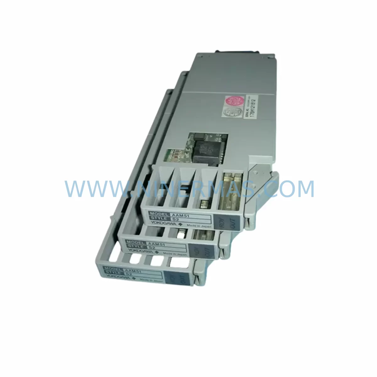
YOKOGAWA AAM51 S2 Service-Ready Spare Part for Industrial Maintenance
Verify the part, confirm the platform family, and move straight into quotation with the right commercial details.
RFQ Ready
- SKUAAM51 S2
- CategoryDCS Distributed Control Systems
- BrandYokogawa
- SupportAvailability, lead time, condition, and shipping coordination
How Buyers Usually Use This Page
- Confirm the exact part number and platform family before sending the quote request.
- Use direct email when quantity, condition, and destination are already defined internally.
- Switch to the broader brand or category archive when you need alternates nearby.
Series Navigation
Move through the most common platform families behind this part.
Product RFQ
Send this part directly for quotation.
Include quantity, required condition, destination country, and target delivery timing. Current reference: YOKOGAWA AAM51 S2 Service-Ready Spare Part for Industrial Maintenance with SKU AAM51 S2.
YOKOGAWA AAM51 S2 Service-Ready Spare Part for Industrial Maintenance
The YOKOGAWA AAM51 S2 is an original analog output module designed for deployment within the CENTUM VP and CENTUM CS 3000 Remote I/O (RIO) distributed control system architecture. As a critical signal-output component, the AAM51 S2 converts digital control signals from the field control station into precise 4–20 mA or 1–5 V analog outputs, driving final control elements such as control valves, variable frequency drives, and positioners across continuous process industries including oil refining, petrochemical, power generation, and pulp and paper manufacturing.
For maintenance engineers managing aging DCS infrastructure, the AAM51 S2 represents a high-priority spare part. Output module failures are among the most disruptive fault categories in process control — a single failed channel can cause a control loop to go open, forcing operators into manual mode and exposing the process to instability. Maintaining at least one verified AAM51 S2 unit in the site spare parts cabinet is a standard recommendation for any facility running CENTUM VP or CS 3000 systems with more than five years of operational history.
Procurement engineers sourcing this module should verify the hardware suffix (S2) against the installed base, as suffix variants may carry different firmware compatibility or terminal block configurations. This unit ships pre-tested against YOKOGAWA factory output specifications and is covered by a 12-month warranty from the date of dispatch.
Spare Maintenance Table
| Parameter | Specification |
|---|---|
| Model | AAM51 S2 |
| Brand | YOKOGAWA |
| Module Type | Analog Output Module |
| Compatible Systems | CENTUM VP, CENTUM CS 3000 (RIO) |
| Output Signal | 4–20 mA / 1–5 V DC |
| Output Channels | 8 channels (typical for AAM51 series) |
| Output Resolution | 13-bit (0.012% of full scale) |
| Load Resistance | ≤ 600 Ω (current output mode) |
| Isolation | Channel-to-channel and channel-to-bus isolation |
| Power Supply | Supplied via RIO bus backplane |
| Operating Temperature | 0°C to 55°C |
| Humidity | 10% to 90% RH (non-condensing) |
| Installation | Plug-in to CENTUM RIO node backplane slot |
| Mounting | RIO node card cage (field enclosure or control room) |
| Origin | Japan |
| Warranty | 12 months from dispatch date |
| Pre-shipment Test | Full functional output verification performed |
Maintenance Planning for Continuous Operation
When scheduling a replacement of the AAM51 S2 during a planned shutdown or emergency callout, maintenance teams should treat the module swap as an opportunity to inspect the surrounding RIO node assembly. The AAB141 or AAB142 RIO node backplane should be checked for oxidized bus connectors and cracked card guides — a degraded backplane can cause intermittent output errors that are misdiagnosed as module faults. Similarly, the ACM12 or ACM22 communication module in the same RIO node should be verified for active heartbeat status before and after the swap, as a communication fault can mask output module recovery.
The AAP135 or AAP145 power supply module feeding the RIO node is another component that warrants inspection during any analog output module replacement. Voltage sag or ripple on the 24 VDC bus can cause output drift or calibration offset on newly installed AAM51 S2 units, leading to unnecessary re-calibration cycles. Confirm bus voltage is within ±2% of nominal before declaring the replacement successful.
On the field wiring side, inspect the terminal block assembly (TB) connected to the AAM51 S2 output channels. Corroded or loose terminals are a common source of 4–20 mA loop errors that persist after module replacement. If the site uses signal isolators or loop-powered barriers between the DCS output and the final control element, verify that the isolator input impedance is within the module’s rated load specification. Zener barriers and galvanic isolators from the same control loop should be tested for leakage current before the loop is returned to automatic mode.
For facilities that also operate YOKOGAWA STARDOM FCN/FCJ controllers or hybrid CENTUM VP / ProSafe-RS safety system architectures, the spare parts strategy should extend to include AAI141 or AAI143 analog input modules in the same RIO node, as input and output modules in the same process loop are often replaced in pairs during major overhauls. The HIS (Human Interface Station) engineering workstation should be used to run a loop test on all eight output channels after installation, confirming that each channel responds correctly to a stepped reference signal before the loop is handed back to operations.
Procurement teams managing multi-site DCS fleets should consider holding a minimum of two AAM51 S2 units per site as rotational spares, particularly for facilities where lead times from the OEM exceed eight weeks. This module is available for long-term supply through established industrial spare parts channels, with consistent stock maintained to support both emergency and planned procurement cycles.
Site Replacement Workflow
Step 1 — Preparation: Confirm the installed module suffix (S2) matches the replacement unit. Download the current loop configuration from the CENTUM VP HIS engineering station and save a backup. Place the affected control loop in manual mode from the operator console.
Step 2 — Safe Isolation: De-energize the RIO node slot using the field control station’s I/O power isolation procedure. Do not remove the module under live bus power unless the node supports hot-swap operation — verify this in the CENTUM VP hardware manual for your node revision.
Step 3 — Module Swap: Extract the faulty AAM51 S2 by releasing the card ejector levers. Insert the replacement module firmly until the bus connector seats fully. Confirm the module status LED transitions from fault (red) to normal (green) within 30 seconds of power restoration.
Step 4 — Loop Verification: From the HIS engineering station, execute a channel-by-channel loop test. Step each output channel from 4 mA to 20 mA and confirm the field instrument (valve positioner, VFD, or indicator) responds correctly. Log the test results in the site maintenance management system.
Step 5 — Return to Service: Transfer the control loop from manual to automatic mode. Monitor the process variable for at least 15 minutes to confirm stable control response. Update the spare parts inventory record to reflect the consumed unit and initiate a replenishment order to restore minimum stock levels.
This workflow is applicable to both emergency replacements during unplanned outages and scheduled replacements during annual turnarounds. The total elapsed time for a trained DCS technician is typically 45–90 minutes, including loop testing.
Spare Parts Support FAQ
Q1: Is the AAM51 S2 compatible with both CENTUM VP and CENTUM CS 3000 systems?
Yes. The AAM51 S2 is designed for the YOKOGAWA RIO (Remote I/O) platform, which is shared across CENTUM VP and CENTUM CS 3000 architectures. However, always verify the node type and backplane revision at your site before installation, as hardware generation differences may affect slot compatibility.
Q2: What does the pre-shipment test cover?
Each AAM51 S2 unit undergoes a full functional output verification prior to dispatch. This includes channel-by-channel output accuracy testing across the 4–20 mA range, isolation resistance measurement, and bus communication handshake confirmation. A test record is available upon request.
Q3: How should the AAM51 S2 be stored if it is held as a long-term rotational spare?
Store the module in its original anti-static packaging in a climate-controlled environment at 15°C to 35°C with relative humidity below 75% (non-condensing). Avoid storage near strong magnetic fields or corrosive atmospheres. Inspect and power-cycle rotational spares at least once every 24 months to verify operational readiness.
Q4: What is the warranty coverage and what does it include?
All AAM51 S2 units supplied carry a 12-month warranty from the date of dispatch. The warranty covers manufacturing defects and functional failures under normal operating conditions. It does not cover damage resulting from incorrect installation, overvoltage events, or physical mishandling. Warranty claims are processed with a target response time of 5 business days.
| Product Series | CENTUM VP |
|---|---|
| Country of Origin | JP |
Catalog Continuation
More Yokogawa modules in the catalog.
Use the brand lane to compare nearby part numbers, platform-adjacent modules, and other inquiry-ready listings before sending your final RFQ.
Catalog Continuation
Alternative parts within DCS Distributed Control Systems.
Stay inside the same system family when you need substitutes, adjacent modules, or a broader shortlist for procurement review.
SKU: High Performance Communication Controller
Honeywell 51401635-150 Service-Ready Spare for C300
SKU: 6DD2920-0AR2 6DD2920-OAR2
Siemens 6DD2920-0AR2 Service-Ready Spare Part for Industrial Maintenance