Original Industrial Spare Part
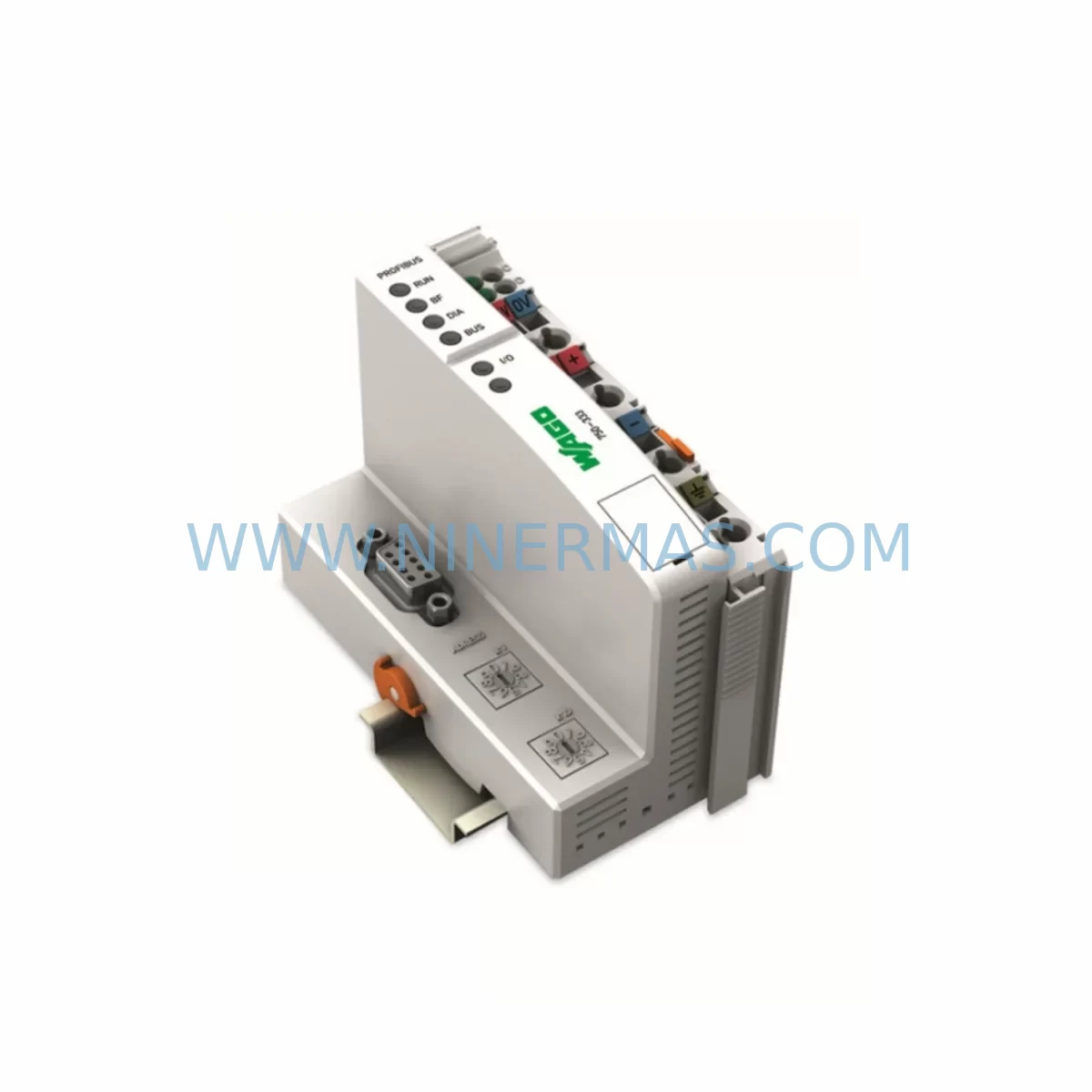
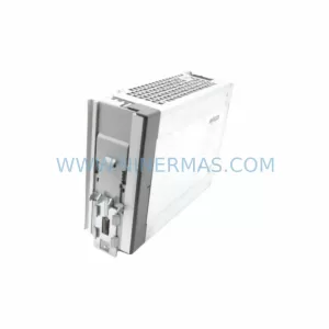
WAGO 750-333 Service-Ready Spare Part for Industrial Maintenance
Verify the part, confirm the platform family, and move straight into quotation with the right commercial details.
RFQ Ready
- SKU750-333
- CategoryPLC & Industrial Automation Modules
- BrandWAGO
- SupportAvailability, lead time, condition, and shipping coordination
How Buyers Usually Use This Page
- Confirm the exact part number and platform family before sending the quote request.
- Use direct email when quantity, condition, and destination are already defined internally.
- Switch to the broader brand or category archive when you need alternates nearby.
Series Navigation
Move through the most common platform families behind this part.
Product RFQ
Send this part directly for quotation.
Include quantity, required condition, destination country, and target delivery timing. Current reference: WAGO 750-333 Service-Ready Spare Part for Industrial Maintenance with SKU 750-333.
WAGO 750-333 Service-Ready Spare Part for Industrial Maintenance
The WAGO 750-333 is a digital output terminal module within the widely deployed WAGO 750 Series modular I/O system. Designed for DIN-rail installation in industrial control cabinets, this module provides reliable digital output capability for programmable logic controller (PLC) applications across manufacturing, process automation, building management, and energy distribution environments. As a service-ready spare part, the WAGO 750-333 is pre-shipment tested and supplied with a 12-month warranty, enabling maintenance engineers and procurement teams to restore system availability with confidence and minimal downtime.
The WAGO 750 Series fieldbus-independent modular I/O platform has been installed across tens of thousands of industrial sites globally. When a 750-333 output module fails or reaches end of service life, rapid replacement is critical to maintaining production continuity. Sourcing a verified, tested spare part from a reliable supplier with confirmed stock availability is the first step in any effective maintenance strategy for this platform.
Spare Maintenance Table
| Parameter | Specification / Detail |
|---|---|
| Part Number | 750-333 |
| Brand | WAGO |
| Series | WAGO 750 Series Modular I/O |
| Module Type | Digital Output Terminal Module |
| Output Channels | 2-channel digital output (24 VDC typical) |
| Output Current | 0.5 A per channel (typical) |
| Installation | DIN-rail, WAGO 750 Series backplane compatible |
| Communication | Fieldbus-independent; compatible with PROFIBUS, CANopen, DeviceNet, Modbus, EtherCAT couplers |
| Operating Temperature | -25°C to +55°C |
| Protection Class | IP20 |
| Compatibility | WAGO 750/753 Series fieldbus couplers and controllers |
| Replacement Scope | Direct module swap; no coupler reconfiguration required |
| Warranty | 12-Month Warranty — all units pre-shipment tested |
| Supply Availability | Long-term stock; reserved inventory program available |
Maintenance Planning for Continuous Operation
Effective maintenance planning for WAGO 750 Series installations requires a holistic view of the control cabinet and the I/O node architecture. When replacing the WAGO 750-333 digital output module, maintenance engineers should simultaneously inspect adjacent modules and system components to prevent secondary failures and reduce the risk of repeat unplanned downtime.
The WAGO 750-333 operates within a node that typically includes a fieldbus coupler such as the WAGO 750-303 (PROFIBUS DP coupler) or the WAGO 750-352 (Modbus TCP coupler), which serves as the communication gateway between the PLC host and the I/O slice assembly. If the coupler firmware is outdated or the coupler itself shows signs of wear, this is an appropriate time to schedule its inspection or replacement alongside the 750-333 module swap.
Digital input modules such as the WAGO 750-400 or WAGO 750-430 are commonly installed in the same node as the 750-333 and share the same internal data bus. Verifying the integrity of these input modules during a planned maintenance window prevents future diagnostic confusion between input and output faults. Similarly, analog input modules like the WAGO 750-452 or WAGO 750-455 should be checked for signal drift or calibration issues if they are part of the same I/O assembly.
Power supply modules, including the WAGO 750-613 system power supply or the WAGO 787-1002 EPSITRON power supply unit, should be inspected for output voltage stability and ripple. An unstable 24 VDC supply is a common root cause of intermittent digital output faults that may be misdiagnosed as module failure. Replacing the 750-333 without verifying the power supply integrity risks repeat failures within a short maintenance cycle.
Terminal wiring connected to the 750-333 output channels should be inspected for insulation degradation, loose ferrules, and corrosion, particularly in high-humidity or chemically aggressive environments. WAGO CAGE CLAMP spring terminals are self-locking, but mechanical stress from vibration or repeated maintenance access can loosen connections over time. Signal isolators or relay output modules installed downstream of the 750-333 should also be verified for correct switching thresholds and contact integrity.
For installations using WAGO e!COCKPIT or WAGO-IO-PRO programming environments, the replacement of the 750-333 module does not require software reconfiguration provided the module type and slot position remain unchanged. However, engineers should confirm the I/O mapping in the PLC program and verify that the HMI display associated with the affected output signals reflects the correct status after module replacement. Any SCADA or DCS system connected via the fieldbus coupler should be monitored for alarm suppression and re-enabled after the replacement is confirmed operational.
Site Replacement Workflow
Replacing the WAGO 750-333 on-site is a straightforward procedure when the correct spare part is available and the replacement workflow is followed systematically. The following steps outline the recommended approach for minimizing downtime and ensuring system compatibility.
Step 1 — Isolation and Safety: De-energize the affected I/O node by switching off the 24 VDC field power supply. Confirm zero voltage at the module terminals using a calibrated multimeter before proceeding. Do not remove the module under live power, as this may damage the internal data bus or adjacent modules.
Step 2 — Module Removal: Disengage the WAGO 750-333 from the DIN rail by releasing the locking mechanism and sliding the module out of the node assembly. Note the wiring connections and label each terminal before disconnection to ensure accurate re-termination.
Step 3 — Inspection of Adjacent Components: Before installing the replacement module, inspect the data bus connectors on adjacent modules for damage or contamination. Verify that the fieldbus coupler is communicating correctly with the host PLC and that no other modules in the node are reporting faults.
Step 4 — Installation of Replacement Module: Insert the new WAGO 750-333 into the correct slot position. Reconnect all field wiring according to the terminal labeling completed in Step 2. Ensure all CAGE CLAMP connections are fully engaged.
Step 5 — Power-Up and Verification: Re-energize the node and confirm that the replacement module is recognized by the fieldbus coupler. Verify output channel status via the PLC program or HMI display. Conduct a functional test of all output channels before returning the system to normal operation.
Step 6 — Documentation: Record the replacement in the site maintenance log, including the date, module serial number, and technician details. Update the spare parts inventory to reflect the consumed unit and initiate a replenishment order to maintain minimum stock levels.
Spare Parts Support FAQ
Q1: Is the WAGO 750-333 compatible with all WAGO 750 Series fieldbus couplers?
A: Yes. The WAGO 750-333 is designed to operate within the WAGO 750 Series modular I/O system and is compatible with all standard 750 Series fieldbus couplers, including PROFIBUS DP, CANopen, DeviceNet, Modbus TCP, and EtherCAT variants. No coupler reconfiguration is required when replacing a like-for-like module in the same slot position.
Q2: What pre-shipment testing is performed on the WAGO 750-333 spare part?
A: Each unit undergoes functional output channel testing, power consumption verification, and data bus communication checks prior to shipment. Units that do not meet original manufacturer specifications are not dispatched. A 12-month warranty is provided from the date of shipment, covering manufacturing defects and functional failures under normal operating conditions.
Q3: How quickly can the WAGO 750-333 be sourced for emergency maintenance situations?
A: We maintain reserved inventory of the WAGO 750-333 to support emergency procurement requirements. Priority dispatch is available for urgent maintenance situations. Contact our sales team at sale@ninermas.com or +0086 187 5021 5667 to confirm current stock availability and lead time for your specific requirement.
Q4: Can a long-term supply agreement be arranged for the WAGO 750-333 to support ongoing maintenance programs?
A: Yes. We offer reserved inventory programs and long-term supply agreements for maintenance teams managing multiple WAGO 750 Series installations. These programs provide guaranteed stock allocation, fixed pricing, and priority fulfillment to reduce procurement risk and ensure spare parts availability throughout the operational life of your automation system.
| Product Series | Other series |
|---|---|
| Country of Origin | DE |
Catalog Continuation
More WAGO modules in the catalog.
Use the brand lane to compare nearby part numbers, platform-adjacent modules, and other inquiry-ready listings before sending your final RFQ.
Catalog Continuation
Alternative parts within PLC & Industrial Automation Modules.
Stay inside the same system family when you need substitutes, adjacent modules, or a broader shortlist for procurement review.