Original Industrial Spare Part
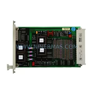
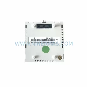
Turck BT-EN-MB2-P Retrofit Ethernet Modbus Module
Verify the part, confirm the platform family, and move straight into quotation with the right commercial details.
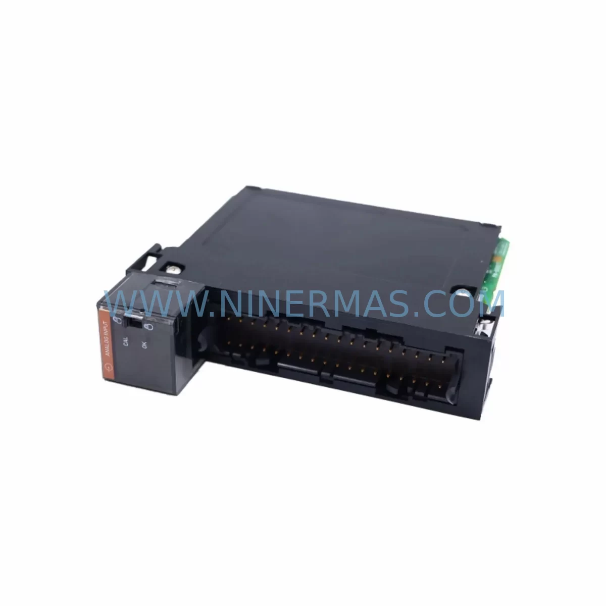
RFQ Ready
- SKUBT-EN-MB2-P
- CategoryPLC & Industrial Automation Modules
- BrandTURCK
- SupportAvailability, lead time, condition, and shipping coordination
How Buyers Usually Use This Page
- Confirm the exact part number and platform family before sending the quote request.
- Use direct email when quantity, condition, and destination are already defined internally.
- Switch to the broader brand or category archive when you need alternates nearby.
Series Navigation
Move through the most common platform families behind this part.
Product RFQ
Send this part directly for quotation.
Include quantity, required condition, destination country, and target delivery timing. Current reference: Turck BT-EN-MB2-P Retrofit Ethernet Modbus Module with SKU BT-EN-MB2-P.
Turck BT-EN-MB2-P Retrofit Ethernet Modbus Module: Legacy System Compatible Upgrade for Industrial Automation
The Turck BT-EN-MB2-P is a ruggedized Ethernet communication module engineered for demanding industrial environments where legacy fieldbus infrastructure must be preserved while transitioning to modern Ethernet-based control architectures. Designed as a retrofit-compatible replacement for discontinued or end-of-life Modbus communication gateways, the BT-EN-MB2-P enables maintenance engineers and system integrators to extend the operational life of existing control cabinets without requiring a full PLC platform migration. Whether you are managing a brownfield retrofit, replacing a failed communication node, or upgrading a legacy production line to support Modbus TCP/IP, this module provides a reliable, tested, and immediately deployable solution backed by a 12-month warranty.
Upgrade Compatibility Table
| Parameter | BT-EN-MB2-P | Legacy Equivalent / Notes |
|---|---|---|
| Communication Protocol | Modbus TCP/IP over Ethernet | Replaces serial Modbus RTU/ASCII gateways; protocol conversion supported |
| Physical Interface | RJ45 Ethernet (10/100 Mbps) | Verify existing cabinet has Ethernet switch or managed hub available |
| Power Supply Input | 24 VDC (nominal) | Confirm existing 24 VDC rail capacity before installation; check PSU load budget |
| Mounting / Form Factor | DIN rail mountable, ruggedized housing | Confirm DIN rail space in control cabinet; compare footprint with replaced module |
| I/O Backplane Interface | Compatible with BL20 and BL67 I/O system backplanes | Verify backplane slot addressing and module sequence before replacement |
| Installation Space | Compact form factor | Measure available cabinet depth and width; confirm cable bend radius for RJ45 |
| Commissioning Tool | Web-based configuration interface / STEP 7 / TIA Portal compatible | Backup existing Modbus register map and IP configuration before swap |
| Warranty | 12 Months | Covered from date of shipment; pre-shipment functional test included |
Retrofit Planning for Existing Automation Systems
Successful integration of the BT-EN-MB2-P into a legacy automation environment requires a structured pre-installation assessment. Before removing the existing communication module, engineers should document the full Modbus register map, IP address assignments, subnet configuration, and any custom function code mappings that the replaced device was handling. This is especially critical in systems where the communication module interfaces directly with a Siemens S7-300 or S7-400 PLC via PROFIBUS-to-Ethernet gateways, or where the module bridges I/O data from a Turck BL20-GW-EN gateway to a supervisory SCADA layer.
In many brownfield installations, the BT-EN-MB2-P is deployed alongside Turck BL20 distributed I/O modules such as the BL20-E-8DI-24VDC digital input module and the BL20-E-4AO-U/I analog output module. These modules share the same backplane bus and must be re-addressed if the gateway module position changes within the rack. Engineers should verify that the module address DIP switch settings or software-assigned node addresses remain consistent with the PLC program’s I/O mapping table before powering up the new configuration.
Power supply capacity is a frequent oversight in retrofit projects. The existing PSU67-12-2420/M or equivalent 24 VDC power supply module must be evaluated for available current headroom. Adding a new Ethernet communication module to an already loaded power rail can cause voltage sag, leading to intermittent communication faults or module resets. A current audit of all connected modules — including signal isolators such as the IMX12-DI intrinsic safety barrier and any TBEN-S1-8DXP compact multiprotocol I/O modules — should be completed before finalizing the retrofit bill of materials.
For systems that include HMI panels communicating over Modbus TCP, the BT-EN-MB2-P replacement must be validated against the HMI’s tag database. Any IP address change or register offset shift will require corresponding updates in the HMI project file. In installations using the BL67-GW-EN Ethernet gateway for remote I/O expansion, the communication chain from the PLC through the gateway to the field devices must be re-verified end-to-end after the module swap. Programming cables such as the Turck PSS67-Cable-USB may be required for initial configuration or firmware verification on site.
Signal isolation requirements should also be reviewed. In mixed-signal environments where analog sensors feed into the I/O system alongside digital control signals, modules like the FCS-G1/2A4P-AP8X flow sensor or the IM18-AI-EX0 inductive sensor may be part of the same control loop. Ensuring that the Modbus polling cycle of the BT-EN-MB2-P is fast enough to capture transient process values from these sensors is essential for maintaining control loop integrity after the retrofit.
Downtime Control During System Migration
Minimizing unplanned downtime is the primary operational constraint in any live production environment retrofit. When replacing the BT-EN-MB2-P or its predecessor module, the recommended approach is to pre-configure the replacement unit offline using a laptop and the module’s web interface before the scheduled maintenance window. This allows the new module to be powered up with the correct IP address, subnet mask, gateway, and Modbus slave table already loaded, reducing on-site commissioning time to a final connectivity check and register verification.
Where possible, a parallel run strategy should be employed: the replacement module is installed in a temporary test rack and connected to a mirrored segment of the network, allowing engineers to validate Modbus read/write cycles against the PLC program without interrupting the live production process. Once validation is confirmed, the physical swap can be executed during a planned micro-shutdown, typically achievable within a 15–30 minute window for a single communication module replacement.
Original PLC program logic should never be modified during the hardware swap phase. All changes to I/O addressing, communication parameters, or function block configurations should be staged in the offline project file and downloaded only after the hardware replacement is confirmed stable. This protects the integrity of the control program and ensures that any rollback to the previous configuration remains possible within the same maintenance window.
Post-installation, a structured commissioning checklist should cover: Ethernet link status confirmation, Modbus TCP connection establishment, register read/write cycle verification, HMI tag refresh validation, and a 30-minute soak test under normal production load before returning the line to full operation.
Retrofit Support FAQ
Q1: Is the BT-EN-MB2-P a direct drop-in replacement for my existing Modbus Ethernet gateway?
A: The BT-EN-MB2-P is designed as a retrofit-compatible replacement for a range of legacy Modbus TCP communication modules. Physical mounting dimensions, DIN rail compatibility, and 24 VDC power input are standardized. However, you should verify the Modbus register map, IP configuration, and backplane slot addressing against your existing system documentation before installation. NINERMAS provides pre-shipment functional testing on all units to confirm communication readiness.
Q2: What commissioning steps are required after installation?
A: After physical installation, connect the module to your Ethernet network and access the web-based configuration interface to assign the correct IP address and Modbus slave parameters. Verify that the PLC program’s I/O mapping matches the module’s register table. Perform a full Modbus read/write cycle test and confirm HMI tag updates before returning the system to production. On-site programming cables may be required for initial firmware verification.
Q3: How do I confirm wiring and terminal compatibility with my existing control cabinet?
A: Review the BT-EN-MB2-P installation manual for terminal block pinout and cable specifications. Compare the RJ45 Ethernet port location and DIN rail footprint against the replaced module. Confirm that existing cable lengths and bend radii are sufficient for the new module’s port positions. For 24 VDC power terminals, verify polarity and torque specifications match your existing wiring standards.
Q4: What does the 12-month warranty cover, and is inventory available for immediate shipment?
A: All BT-EN-MB2-P units supplied by NINERMAS carry a 12-month warranty from the date of shipment, covering manufacturing defects and functional failures under normal operating conditions. Each unit undergoes pre-shipment functional testing to verify communication performance before dispatch. NINERMAS maintains reserved inventory for this SKU to support urgent retrofit and emergency replacement requirements. Contact our team for lead time confirmation and bulk order availability.
| Product Series | Other series |
|---|---|
| Country of Origin | DE |
Catalog Continuation
More TURCK modules in the catalog.
Use the brand lane to compare nearby part numbers, platform-adjacent modules, and other inquiry-ready listings before sending your final RFQ.
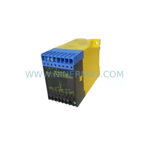
Catalog Continuation
Alternative parts within PLC & Industrial Automation Modules.
Stay inside the same system family when you need substitutes, adjacent modules, or a broader shortlist for procurement review.
SKU: TRY/PRG/4-20MA/10-30DC
MOORE TRY/PRG/4-20MA/10-30DC Service-Ready Spare Part
SKU: 5085-404901-11 12INCH 2910-202413-12 404200XRMPD2H14 7-249717
TEL 5085-404901-11 Service-Ready Spare Part for Industrial Maintenance
SKU: DIP011 05-058-011
SIGMATEK DIP011 05-058-011 Service-Ready Spare Part