Original Industrial Spare Part
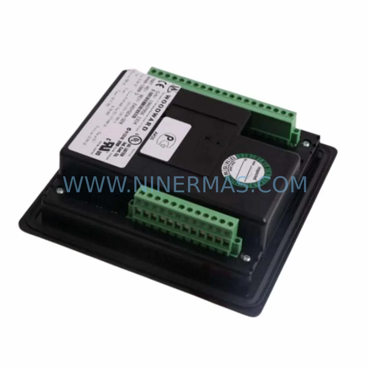
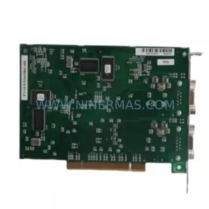
SST SST-PFB-PLC5 Retrofit-Compatible PROFIBUS Module for Legacy Systems
Verify the part, confirm the platform family, and move straight into quotation with the right commercial details.
RFQ Ready
- SKUSST-PFB-PLC5
- CategoryPLC & Industrial Automation Modules
- BrandSST
- SupportAvailability, lead time, condition, and shipping coordination
How Buyers Usually Use This Page
- Confirm the exact part number and platform family before sending the quote request.
- Use direct email when quantity, condition, and destination are already defined internally.
- Switch to the broader brand or category archive when you need alternates nearby.
Series Navigation
Move through the most common platform families behind this part.
Product RFQ
Send this part directly for quotation.
Include quantity, required condition, destination country, and target delivery timing. Current reference: SST SST-PFB-PLC5 Retrofit-Compatible PROFIBUS Module for Legacy Systems with SKU SST-PFB-PLC5.
SST SST-PFB-PLC5 Retrofit-Compatible PROFIBUS Module for Legacy Systems
The SST-PFB-PLC5 is a PROFIBUS DP master/slave communication module engineered specifically for Allen-Bradley PLC-5 series controllers. As aging PLC-5 platforms approach end-of-life and original PROFIBUS interface cards become increasingly scarce, the SST-PFB-PLC5 provides a proven, retrofit-compatible solution that restores full PROFIBUS DP network connectivity without requiring a complete controller overhaul. Whether you are managing a long-running process line in oil and gas, chemical processing, water treatment, or discrete manufacturing, this module allows your existing PLC-5 rack infrastructure to continue communicating with field devices, drives, remote I/O stations, and instrumentation clusters on the PROFIBUS DP network.
The SST-PFB-PLC5 occupies a standard PLC-5 I/O chassis slot and interfaces directly with the PLC-5 backplane, eliminating the need for external gateways or protocol converters in most retrofit scenarios. It supports PROFIBUS DP data rates up to 12 Mbps and is compatible with GSD-based device configuration, making it straightforward to integrate with existing PROFIBUS master configurations managed through STEP 7, TIA Portal, or third-party PROFIBUS configuration tools. For sites where the original SST or Woodhead PROFIBUS card has failed or is no longer available through OEM channels, the SST-PFB-PLC5 represents a direct functional replacement that preserves existing ladder logic, I/O mapping, and HMI screen references without requiring program restructuring.
Each unit is pre-shipment tested against PROFIBUS DP protocol compliance standards and ships with a 12-month warranty covering manufacturing defects and functional failures under normal operating conditions. Stock is maintained to support urgent spare parts requirements and planned maintenance windows.
Upgrade Compatibility Table
| Parameter | SST-PFB-PLC5 (Replacement) | Original / Legacy Card |
|---|---|---|
| Compatible Controller | Allen-Bradley PLC-5 Series | Allen-Bradley PLC-5 Series |
| Backplane Interface | PLC-5 I/O Chassis Slot (standard) | PLC-5 I/O Chassis Slot |
| Communication Protocol | PROFIBUS DP (Master / Slave) | PROFIBUS DP |
| Max Data Rate | Up to 12 Mbps | Up to 12 Mbps |
| GSD Device Support | Yes – standard GSD file import | Yes |
| Installation Space | Single I/O chassis slot | Single I/O chassis slot |
| Terminal / Connector | DB9 PROFIBUS connector (standard) | DB9 PROFIBUS connector |
| Program Compatibility | Existing PLC-5 ladder logic retained | N/A (original) |
| HMI Screen Impact | No screen rebuild required | N/A |
| Commissioning Requirement | PROFIBUS address reassignment + GSD reload | Factory configured |
| Warranty | 12 Months | OEM warranty (expired) |
| Availability | In Stock – Ready to Ship | Discontinued / Scarce |
Retrofit Planning for Existing Automation Systems
Successful integration of the SST-PFB-PLC5 into an existing PLC-5 control system begins with a thorough audit of the current rack configuration. Engineers should document the chassis slot assignments for all installed modules — including analog input cards, digital output modules, and any existing communication cards — before removing the legacy PROFIBUS interface. The SST-PFB-PLC5 requires a single available I/O slot in the PLC-5 chassis; if the rack is fully populated, slot reallocation or chassis expansion using a 1771 I/O chassis extender may be necessary.
Power budget verification is a critical pre-installation step. The PLC-5 power supply — commonly a 1771-P4S or 1771-P7 — must have sufficient backplane current capacity to support the SST-PFB-PLC5 alongside existing modules such as 1771-IFE analog input cards, 1771-OFE analog output cards, and 1771-IBD digital input modules. If the power supply is operating near its rated capacity, a power supply upgrade or load redistribution across a secondary chassis should be planned before the retrofit window opens.
On the PROFIBUS network side, the existing DB9 trunk cable and termination resistors should be inspected and confirmed intact. The SST-PFB-PLC5 node address must be assigned to match the address previously held by the failed card, ensuring that the PROFIBUS master — whether a Siemens S7-300 CP 342-5, a Siemens ET 200M IM 153-2, or a third-party PROFIBUS master controller — continues to poll the correct station address without requiring a full network reconfiguration. If the PROFIBUS master configuration was built in STEP 7 or TIA Portal, the GSD file for the SST-PFB-PLC5 should be imported and the device substituted in the hardware configuration before going online.
Within the PLC-5 program, the data table addresses mapped to the original PROFIBUS card’s I/O image should be verified against the SST-PFB-PLC5 data mapping documentation. In most cases, the input and output data block structure is preserved, allowing existing ladder logic rungs referencing N7, F8, or B3 data files to remain unchanged. If the site uses a PanelView 550 or PanelView 900 HMI connected via DH+ or Remote I/O, the HMI tag database and screen animations linked to PROFIBUS-sourced data values should be validated in offline simulation before the live cutover.
For sites running a 1785-L80B or 1785-L60B PLC-5 processor, the SST-PFB-PLC5 has been validated for compatibility with standard PLC-5 I/O scan configurations. Sites using a 1771-ACN15 ControlNet adapter or a 1771-ACNR15 redundant ControlNet adapter in the same chassis should confirm slot addressing does not conflict with the new PROFIBUS module assignment. Signal isolators such as the P+F KFD2-STC4-Ex1 may be required on PROFIBUS segments running through hazardous area boundaries, and their installation should be factored into the retrofit schedule.
Programming cables such as the 1784-U2DHP USB-to-DH+ adapter are recommended for online program verification during commissioning. The retrofit plan should also account for any 1771-SDN DeviceNet scanner cards sharing the chassis, as slot scan time allocation may need adjustment after the PROFIBUS module is installed and the I/O scan list is updated.
Downtime Control During System Migration
Minimizing unplanned downtime during a PLC-5 PROFIBUS module replacement requires a structured migration approach that protects existing program logic and maintains field control continuity throughout the changeover. The recommended practice is to perform a full online backup of the PLC-5 processor program using RSLogix 5 before any hardware is disturbed. This backup should be stored on a local engineering workstation and verified by performing an offline compare against the processor’s current program to confirm the backup is complete and uncorrupted.
Where process conditions allow, the PROFIBUS network segment served by the failed module should be placed in a safe fallback state — with field devices such as variable frequency drives, solenoid valve banks, and remote I/O stations set to their defined fault states — before the chassis is de-energized. This prevents uncontrolled actuator movement during the slot swap. The SST-PFB-PLC5 can typically be installed and the chassis re-energized within a 30–60 minute maintenance window, provided the PROFIBUS node address is pre-configured and the GSD file is already loaded in the master configuration.
After power restoration, the PROFIBUS master should be brought online first to confirm that the SST-PFB-PLC5 is recognized at the correct station address and that all slave devices are reporting healthy status. The PLC-5 processor should then be placed in Remote Program mode, the verified backup program downloaded, and the processor transitioned to Remote Run mode with the I/O scan enabled. HMI screens should be monitored for correct data refresh on all PROFIBUS-sourced analog and digital values before the process is returned to automatic control.
For critical continuous processes where even a brief interruption is unacceptable, a parallel commissioning approach — where the SST-PFB-PLC5 is pre-configured and tested in a bench environment replicating the target chassis configuration — is strongly recommended. This approach reduces live commissioning time to the minimum required for physical installation and final address verification, typically under 20 minutes.
Retrofit Support FAQ
Q1: Is the SST-PFB-PLC5 a direct drop-in replacement for the original SST PROFIBUS card in a PLC-5 chassis?
A: Yes. The SST-PFB-PLC5 is designed as a functional replacement for the original SST and Woodhead PROFIBUS DP interface cards used in Allen-Bradley PLC-5 systems. It occupies the same single I/O chassis slot, uses the same DB9 PROFIBUS connector, and supports the same PROFIBUS DP master/slave operating modes. Existing PLC-5 ladder logic and HMI configurations do not require modification in standard replacement scenarios.
Q2: What commissioning steps are required after installing the SST-PFB-PLC5?
A: After physical installation, the PROFIBUS node address must be set to match the address previously assigned to the failed card. The GSD file for the SST-PFB-PLC5 should be imported into the PROFIBUS master configuration tool (STEP 7, TIA Portal, or equivalent), and the device substituted in the hardware configuration. The PROFIBUS master should be brought online to confirm slave recognition before the PLC-5 processor is returned to Run mode. A full I/O scan verification and HMI data validation should be completed before returning the process to automatic control.
Q3: Has the SST-PFB-PLC5 been tested before shipment, and what warranty is provided?
A: Every SST-PFB-PLC5 unit undergoes pre-shipment functional testing against PROFIBUS DP protocol compliance standards prior to dispatch. Each unit ships with a 12-month warranty covering manufacturing defects and functional failures under normal operating conditions. Warranty support is provided directly through NINERMAS COMPANY LIMITED.
Q4: What is the typical lead time, and is stock available for urgent requirements?
A: Stock is maintained to support both planned maintenance programs and urgent unplanned replacement requirements. Standard orders are processed and dispatched within 1–3 business days. For critical plant shutdowns or emergency spare parts requirements, please contact our team directly to confirm current stock availability and expedited shipping options.
| Product Series | Legacy |
|---|
Catalog Continuation
Likely PLC-5 platform matches.
These parts are closer to the same platform family signaled by the current SKU and title, so buyers can validate continuity before sending a final RFQ.
Catalog Continuation
More SST modules in the catalog.
Use the brand lane to compare nearby part numbers, platform-adjacent modules, and other inquiry-ready listings before sending your final RFQ.
Catalog Continuation
Alternative parts within PLC & Industrial Automation Modules.
Stay inside the same system family when you need substitutes, adjacent modules, or a broader shortlist for procurement review.
SKU: PFXPP170CA66K00N00
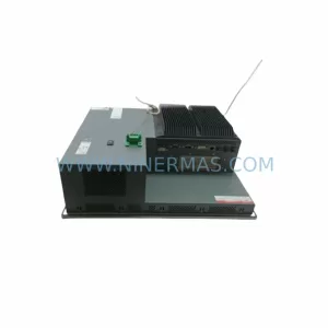
Pro-face PFXPP170CA66K00N00 Service-Ready Spare Part

SKU: 6SL3224-0BE32-2UA0
Siemens 6SL3224-0BE32-2UA0 Retrofit PM240 Power Module