Original Industrial Spare Part
Siemens 6SE7031-8EF84-1JC1 Spare Part for MASTERDRIVES
Verify the part, confirm the platform family, and move straight into quotation with the right commercial details.
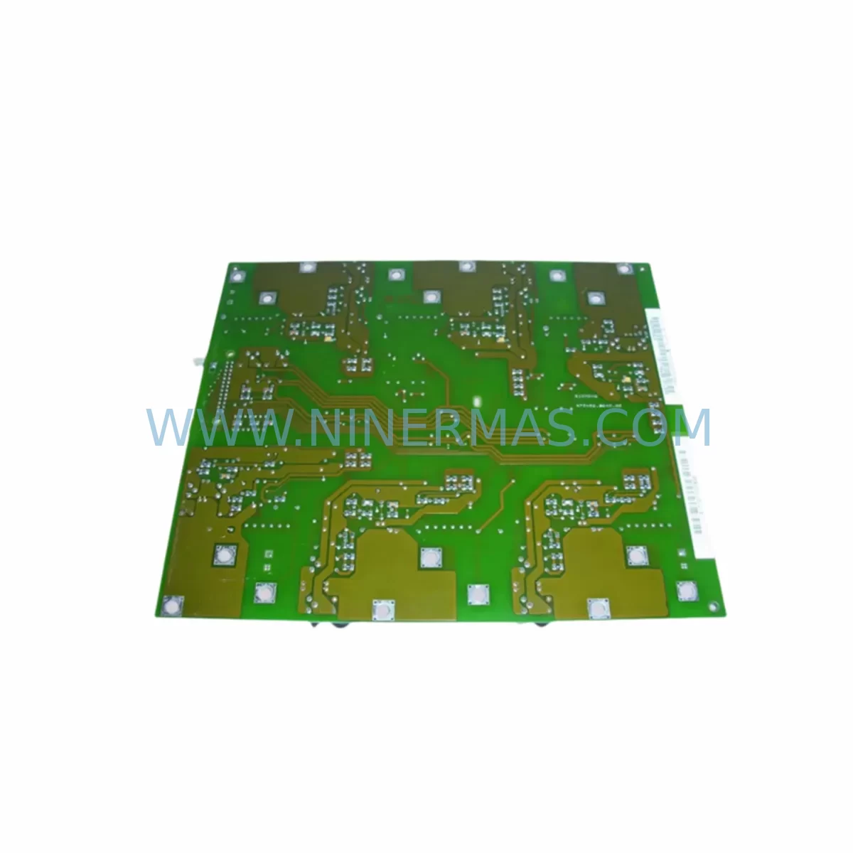
RFQ Ready
- SKU6SE7031-8EF84-1JC1
- CategoryPLC & Industrial Automation Modules
- BrandSiemens
- SupportAvailability, lead time, condition, and shipping coordination
How Buyers Usually Use This Page
- Confirm the exact part number and platform family before sending the quote request.
- Use direct email when quantity, condition, and destination are already defined internally.
- Switch to the broader brand or category archive when you need alternates nearby.
Series Navigation
Move through the most common platform families behind this part.
Product RFQ
Send this part directly for quotation.
Include quantity, required condition, destination country, and target delivery timing. Current reference: Siemens 6SE7031-8EF84-1JC1 Spare Part for MASTERDRIVES with SKU 6SE7031-8EF84-1JC1.
Siemens 6SE7031-8EF84-1JC1 Spare Part for MASTERDRIVES: Spare Part Replacement and Downtime Risk Control
The Siemens 6SE7031-8EF84-1JC1 is a service-ready spare part unit from the SIMOVERT MASTERDRIVES series — Siemens’ established platform for variable-speed AC drive applications in heavy industrial environments. This unit is rated for high-power motor control duties and is widely deployed in steel mills, paper machines, cement plants, water treatment facilities, and automated production lines where continuous operation is non-negotiable.
For maintenance engineers managing aging drive cabinets, the 6SE7031-8EF84-1JC1 represents a direct-fit replacement option that preserves existing wiring topology, parameter sets, and motor compatibility without requiring a full system redesign. Procurement engineers sourcing this part benefit from a verified supply chain, pre-shipment functional testing, and a 12-month warranty that covers the full post-installation period.
Every unit dispatched from our warehouse undergoes pre-shipment inspection covering power stage integrity, gate driver function, DC bus capacitor condition, and control board communication. This ensures that the replacement unit arrives site-ready, reducing commissioning time and eliminating the risk of installing a defective spare into a live production environment.
Spare Maintenance Table
| Parameter | Specification / Detail |
|---|---|
| Part Number | 6SE7031-8EF84-1JC1 |
| Brand | Siemens |
| Series | SIMOVERT MASTERDRIVES MC/VC |
| Product Type | AC Variable Frequency Drive (VFD) / Frequency Inverter |
| Output Power | ~160 kW (inferred from SKU designation 31-8EF84) |
| Supply Voltage | 3-phase 380–480 V AC (±10%) |
| Output Frequency | 0–300 Hz (application-dependent) |
| Control Mode | Vector Control (VC) / Motion Control (MC) |
| Communication | PROFIBUS-DP via CBP2 option board (6SE7090-0XX84-0FF5) |
| Cooling Method | Forced air cooling (internal fan) |
| Protection Class | IP20 (cabinet-mount) |
| Ambient Temperature | 0°C to +40°C operating; up to +50°C with derating |
| Compatibility | Direct replacement for 6SE7031-8EF84-1JC1; compatible with MASTERDRIVES MC/VC cabinet systems |
| Installation | Cabinet-mount; DIN rail or panel mount per original mechanical footprint |
| Origin | Germany (OEM production) |
| Warranty | 12 months from date of shipment |
| Pre-Shipment Test | Power stage, gate driver, DC bus, control board communication verified |
| Condition | New / Refurbished-to-OEM-spec (confirmed at order) |
Maintenance Planning for Continuous Operation
When replacing the 6SE7031-8EF84-1JC1 in a MASTERDRIVES cabinet, a disciplined maintenance engineer will not stop at the drive unit itself. The surrounding electrical ecosystem must be inspected and validated to prevent repeat failures and ensure the replacement unit operates within its rated parameters from day one.
Begin with the input power supply: verify that the incoming 3-phase supply voltage is within the ±10% tolerance band and that phase imbalance does not exceed 2%. A degraded supply is one of the leading causes of premature drive failure. Inspect the input line reactor (e.g., 4EP3600-8US or equivalent Siemens line choke) for signs of overheating or insulation breakdown.
Check the DC bus fuses and pre-charge resistors within the cabinet. These components absorb inrush current during power-up and are frequently overlooked during emergency replacements. A failed pre-charge circuit will damage a new drive unit within the first power cycle.
Inspect all terminal blocks and power wiring on the motor output side. Loose connections at U2, V2, W2 terminals generate localized heating that degrades insulation and introduces ground fault risk. Torque all terminals to the manufacturer’s specification before energizing.
For systems using PROFIBUS-DP communication, verify the CBP2 communication board (6SE7090-0XX84-0FF5) is seated correctly and that the bus termination resistors are active at both ends of the segment. A misconfigured PROFIBUS segment will prevent the drive from receiving speed references from the PLC or DCS, causing a no-run fault that is easily misdiagnosed as a drive hardware failure.
Review the I/O wiring at the CU (Control Unit) board. Analog input signals (0–10 V or 4–20 mA speed references) should be checked for signal integrity using a calibrated meter. Digital inputs for RUN, STOP, FAULT RESET, and direction commands must be verified against the parameter set loaded in the replacement unit. If the original parameter set was not backed up, re-commissioning will be required using SIMOVIS or DriveMonitor software.
Where the system includes signal isolators between the PLC analog output and the drive analog input, inspect these for drift or failure — a faulty isolator will cause erratic speed control even with a perfectly functional drive. Similarly, check any output filters or dV/dt reactors on the motor cable for physical damage.
For cabinet-level inspection, examine the 24 V DC auxiliary power supply (e.g., SITOP PSU100S or equivalent) that powers the control electronics. An under-voltage condition on the 24 V rail will cause intermittent control faults that are difficult to trace without a power quality meter. Also inspect relay output modules used for fault signaling and motor contactor control — contact wear on these relays is a common source of unreliable fault acknowledgment.
If the installation includes an HMI panel (such as a Siemens OP7, OP17, or TP177) connected to the drive via MPI or PROFIBUS, verify that the HMI firmware and screen configuration are compatible with the replacement drive’s firmware version. Firmware mismatches can cause parameter display errors or prevent remote parameter changes from the HMI.
Finally, review the backplane and rack connections if the drive is part of a modular MASTERDRIVES cabinet system. Ensure that the rack bus connector is clean and fully engaged, and that adjacent modules — such as the Rectifier Unit (e.g., 6SE7031-2EF85-1AA0) and the Braking Unit — are functioning correctly before returning the system to production.
Site Replacement Workflow
Step 1 — Isolation and lockout: De-energize the cabinet following site LOTO procedures. Verify DC bus voltage has discharged below 50 V before opening the cabinet door. DC bus discharge on high-power MASTERDRIVES units can take 5–10 minutes after mains disconnection.
Step 2 — Parameter backup: If the existing unit is still partially functional, connect a laptop running DriveMonitor or STARTER software and perform a full parameter upload (P0010 = 30, then upload via serial or PROFIBUS). Store the parameter file with the equipment tag number and date.
Step 3 — Mechanical removal: Disconnect all power cables (L1/L2/L3 input, U2/V2/W2 motor output, DC bus links if applicable) and all control wiring at the CU board. Label all connectors before removal. Remove the drive unit from the cabinet rail or mounting frame.
Step 4 — Replacement unit installation: Mount the 6SE7031-8EF84-1JC1 replacement unit in the original position. Reconnect all power and control wiring in reverse order. Verify torque on all power terminals.
Step 5 — Parameter restore and commissioning: Download the backed-up parameter set to the replacement unit. Verify motor data parameters (P0300–P0350 range) match the nameplate of the connected motor. Set the ramp times, current limits, and protection thresholds to match the original configuration.
Step 6 — No-load test: Energize the cabinet and perform a no-load run at low speed (5–10 Hz) to verify control response, analog input scaling, and digital I/O function before connecting the mechanical load.
Step 7 — Load test and handover: Run the drive under full production load for a minimum of 30 minutes. Monitor output current, DC bus voltage, heatsink temperature, and fault log. Document the commissioning results and update the equipment maintenance record.
This workflow minimizes total downtime to typically 2–4 hours for a prepared maintenance team, compared to 1–3 days when sourcing a replacement unit without a pre-tested spare in stock.
Spare Parts Support FAQ
Q1: Is the 6SE7031-8EF84-1JC1 a direct drop-in replacement for the original unit?
Yes. The replacement unit shares the same mechanical footprint, terminal layout, and electrical ratings as the original 6SE7031-8EF84-1JC1. No cabinet modifications are required. Parameter re-loading is necessary if the original parameter set was not pre-loaded at the factory.
Q2: What does the 12-month warranty cover?
The 12-month warranty covers manufacturing defects and functional failures under normal operating conditions from the date of shipment. It does not cover damage caused by incorrect installation, supply voltage exceedances, or environmental conditions outside the rated specification. All warranty claims are supported with a replacement-first policy to minimize your downtime.
Q3: How do you verify compatibility before shipment?
Each unit is cross-referenced against the original Siemens part number and series designation. Pre-shipment testing covers power stage function, gate driver integrity, DC bus capacitor condition, and control board communication. A test report is available upon request for critical applications.
Q4: Can you support long-term supply for annual maintenance contracts?
Yes. We maintain stock of MASTERDRIVES series spare parts and can support blanket purchase orders, annual maintenance contracts, and emergency same-day dispatch for critical production sites. Contact our team to discuss volume pricing and reserved stock arrangements for your facility.
| Product Series | SIMOVERT |
|---|---|
| Country of Origin | DE |
Catalog Continuation
More Siemens modules in the catalog.
Use the brand lane to compare nearby part numbers, platform-adjacent modules, and other inquiry-ready listings before sending your final RFQ.
SKU: ES7151-1AA05-0AB0
SIEMENS 6ES7151-1AA05-0AB0 Retrofit-Compatible IM for Legacy ET200S
SKU: 6SL3420-2TE11-7AA1
Siemens 6SL3420-2TE11-7AA1 Safety-Reliable Drive for Critical Control Sites
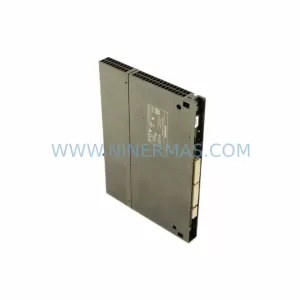
SKU: 6GK7443-5DX05-0XE1
Siemens 6GK7443-5DX05-0XE1 Retrofit-Compatible CP for Legacy Systems
Catalog Continuation
Alternative parts within PLC & Industrial Automation Modules.
Stay inside the same system family when you need substitutes, adjacent modules, or a broader shortlist for procurement review.
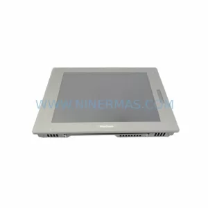
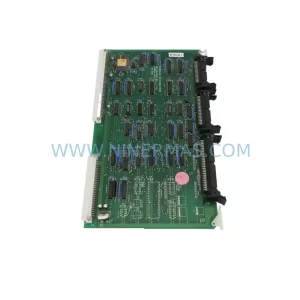
SKU: 80E 208-501035-6 281-501035-7 RPCON-56P RGW-DV C2000 GOT1000 , GT1575-VTBA GT15-75QBUSL
TEL 80E-208-501035-6 Service-Ready Industrial Spare Part
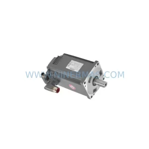
SKU: DC522 1SAP240600R0001
ABB DC522 1SAP240600R0001 Service-Ready Spare Part