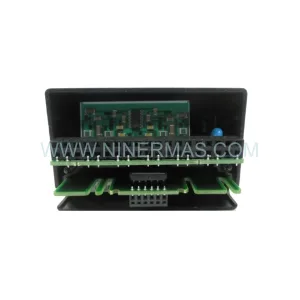
Original Industrial Spare Part
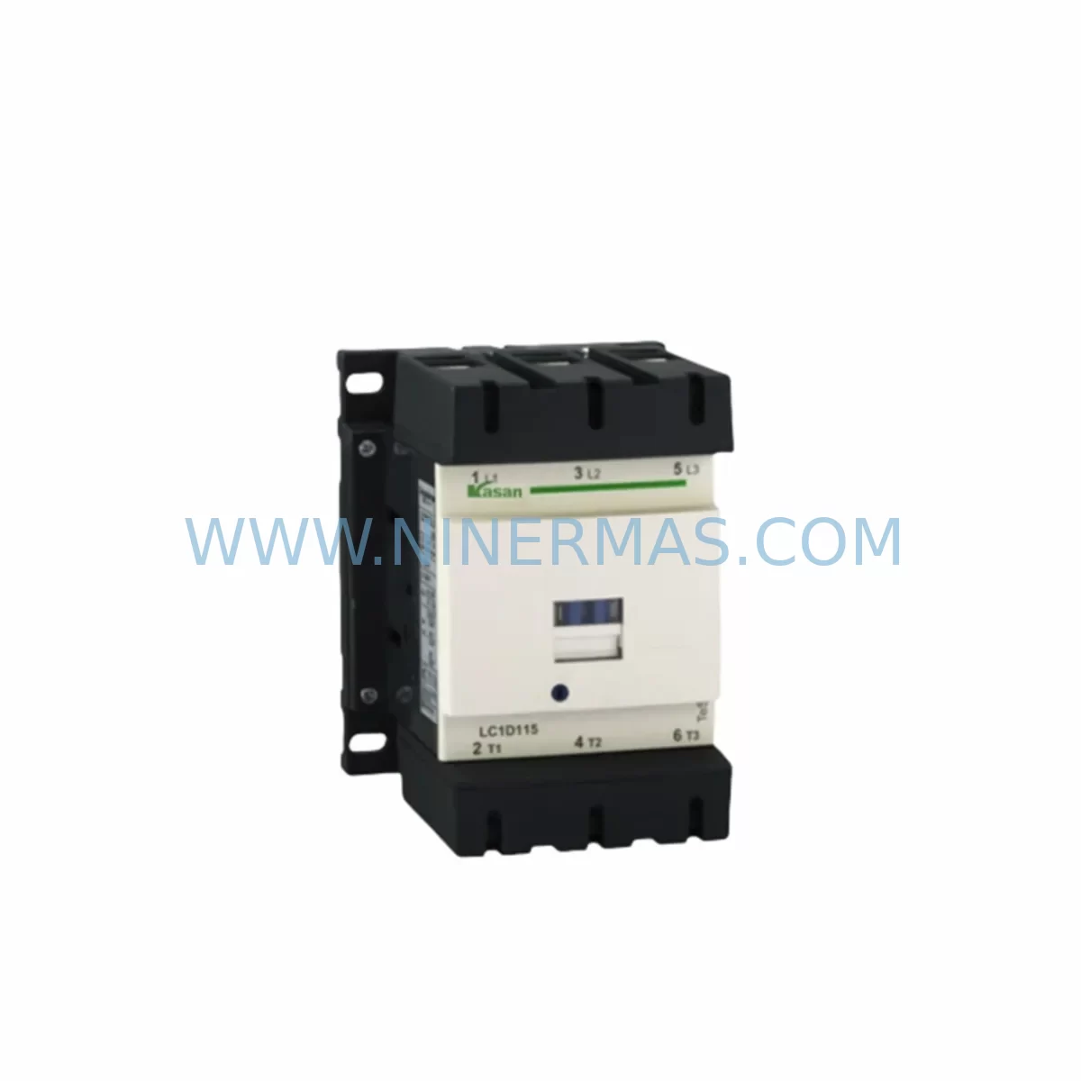
Schneider LC1D115M7C Retrofit-Compatible Contactor for Legacy
Verify the part, confirm the platform family, and move straight into quotation with the right commercial details.
RFQ Ready
- SKULC1D115M7C
- CategoryPLC & Industrial Automation Modules
- BrandSchneider Electric
- SupportAvailability, lead time, condition, and shipping coordination
How Buyers Usually Use This Page
- Confirm the exact part number and platform family before sending the quote request.
- Use direct email when quantity, condition, and destination are already defined internally.
- Switch to the broader brand or category archive when you need alternates nearby.
Series Navigation
Move through the most common platform families behind this part.
Product RFQ
Send this part directly for quotation.
Include quantity, required condition, destination country, and target delivery timing. Current reference: Schneider LC1D115M7C Retrofit-Compatible Contactor for Legacy with SKU LC1D115M7C.
Schneider LC1D115M7C Retrofit-Compatible Contactor for Legacy Systems
The Schneider Electric LC1D115M7C is a 115A three-pole AC contactor from the TeSys D series, engineered for demanding industrial control applications. As legacy automation systems age and original components reach end-of-life, the LC1D115M7C has become a critical retrofit solution for engineers and maintenance teams tasked with modernizing motor control centers, control cabinets, and distributed drive panels without full system replacement. Its standardized DIN rail mounting footprint, coil voltage flexibility (220V AC, 50/60 Hz), and IEC 60947-4-1 compliance make it a preferred drop-in replacement across a wide range of existing installations.
Whether you are replacing a discontinued LC1D95M7C or stepping up from a LC1D80M7C in an upgraded motor starter assembly, the LC1D115M7C integrates directly into existing wiring schemes with minimal modification. Engineers retrofitting older Telemecanique-branded panels will find that the terminal layout, mounting hole pattern, and auxiliary contact interface remain consistent with earlier TeSys D generation devices, significantly reducing rewiring time and the risk of field errors during changeover.
Upgrade Compatibility Table
| Parameter | LC1D115M7C | Retrofit Notes |
|---|---|---|
| Rated Current (AC-3) | 115A | Verify motor FLA and cable sizing before swap |
| Coil Voltage | 220V AC, 50/60 Hz | Confirm control circuit voltage matches existing wiring |
| Mounting | DIN Rail / Screw | Compatible with standard 35mm DIN rail in legacy cabinets |
| Auxiliary Contacts | 1NO + 1NC (standard) | Add LA1DN11 auxiliary contact block if more I/O needed |
| Communication Compatibility | Standalone / Relay Logic | Pair with TeSys T LTM R for Modbus RTU motor management |
| Overload Relay Interface | Direct mount | Compatible with LRD340 thermal overload relay (30–40A adj.) |
| Replacement for | LC1D95M7C, LC1D80M7C | Upward-compatible; verify contactor frame size in cabinet |
| Installation Space | Standard TeSys D footprint | Confirm vertical clearance for top/bottom cable entry |
| Warranty | 12-Month Warranty — Covered from date of shipment | |
Retrofit Planning for Existing Automation Systems
Successful integration of the LC1D115M7C into a legacy system begins well before the contactor arrives on site. Retrofit planning must account for the full control architecture surrounding the device. In many older motor control centers, the LC1D115M7C will be installed alongside a LRD3359 or LRD340 thermal overload relay, which mounts directly to the contactor’s lower terminal block without additional hardware. Engineers should verify the overload relay’s trip class and current adjustment range against the motor nameplate data before committing to the assembly.
For systems that include a Schneider Modicon M340 or Modicon Premium PLC as the primary controller, the LC1D115M7C is typically driven through a discrete output module such as the BMX DDO 3202K or equivalent DO card. Confirm that the output module’s current sourcing capacity is sufficient to energize the contactor coil at 220V AC, and that the PLC program logic correctly handles the auxiliary feedback contact wired back to a digital input — commonly a BMX DDI 1602 — for run confirmation and fault detection.
In installations where the legacy system used a Telemecanique CAD32M7C control relay to sequence the contactor, the same relay can typically be retained, as the coil interface and auxiliary contact wiring remain compatible. However, if the control cabinet is being upgraded to include a Zelio Logic SR3B261BD smart relay for local sequencing, the LC1D115M7C’s coil can be driven directly from the relay’s transistor or relay output, provided the output rating matches the coil inrush current.
Where communication protocol migration is part of the retrofit scope — for example, transitioning from hardwired relay logic to a Profibus DP or Modbus RTU network — the LC1D115M7C can be paired with a TeSys T LTM R motor management relay, which provides network-addressable motor protection, current monitoring, and remote start/stop capability. This combination is particularly effective in upgrading legacy star-delta starter panels where individual contactors previously operated on timer-based relay logic with no remote visibility.
For I/O expansion in retrofitted control cabinets, engineers frequently add a Schneider XPSAF5130 safety relay or a dedicated safety PLC module to supervise the LC1D115M7C’s operation in emergency stop circuits, ensuring compliance with updated machinery safety standards without replacing the entire control panel. Terminal block compatibility should be verified against existing Schneider NSYTRV or equivalent terminal rail assemblies to avoid rework during installation.
Downtime Control During System Migration
Minimizing production downtime during a contactor retrofit requires a structured changeover plan. Before de-energizing the panel, photograph or document the existing terminal wiring, including the main power terminals (L1/L2/L3 and T1/T2/T3), the coil terminals (A1/A2), and all auxiliary contact connections. This documentation protects the original program logic and HMI screen assignments from being disrupted by wiring errors during reinstallation.
Where possible, pre-assemble the LC1D115M7C with its overload relay and auxiliary contact block on a temporary DIN rail section before the scheduled maintenance window. This allows the new assembly to be dropped into the cabinet and wired in a single operation, reducing the time the panel is de-energized. For systems controlled by a Modicon or similar PLC, retain the existing program in the controller memory and avoid downloading a new program version until the mechanical installation has been verified and the motor has been jogged under no-load conditions.
After installation, perform a continuity check on all power and control terminals before re-energizing. Verify that the HMI run/fault status displays update correctly when the contactor is manually energized from the control circuit. Confirm that the overload relay trip test function operates correctly and that the PLC fault register clears on reset. A structured commissioning checklist — covering power terminal torque, coil voltage measurement, auxiliary contact function test, and overload relay calibration — ensures that the retrofit is completed safely and that the system is returned to full production capability with confidence.
Retrofit Support FAQ
Q1: Is the LC1D115M7C a direct replacement for the LC1D95M7C?
The LC1D115M7C is upward-compatible with the LC1D95M7C in most applications. The physical mounting footprint and terminal layout are consistent within the TeSys D frame range. However, engineers should verify that the upstream cable sizing, fuse rating, and overload relay setting are adjusted to match the LC1D115M7C’s 115A rated current before energizing the replacement assembly.
Q2: What pre-shipment testing is performed on the LC1D115M7C?
Each unit undergoes coil energization testing, main contact resistance verification, and auxiliary contact function testing prior to shipment. Units are inspected for mechanical integrity and packaged to prevent transit damage. A test report is available upon request for critical infrastructure applications.
Q3: What is the stock availability and lead time?
The LC1D115M7C is maintained in stock for immediate dispatch. Orders placed before the daily cut-off are typically shipped the same business day. For large-quantity orders or project-based procurement, please contact our sales team to confirm allocation and delivery scheduling.
Q4: What warranty coverage applies to the LC1D115M7C?
All units are covered by a 12-month warranty from the date of shipment. The warranty covers manufacturing defects and component failures under normal operating conditions. Our technical support team is available to assist with installation queries, compatibility verification, and warranty claims throughout the coverage period.
| Product Series | TeSys |
|---|---|
| Country of Origin | FR |
Catalog Continuation
More Schneider Electric modules in the catalog.
Use the brand lane to compare nearby part numbers, platform-adjacent modules, and other inquiry-ready listings before sending your final RFQ.
Catalog Continuation
Alternative parts within PLC & Industrial Automation Modules.
Stay inside the same system family when you need substitutes, adjacent modules, or a broader shortlist for procurement review.
SKU: 6FC5357-0BB12-0AE0
Siemens 6FC5357-0BB12-0AE0 Service-Ready Industrial Spare Part
SKU: 3BSE011790R1(PXHK401)
ABB 3BSE011790R1 PXHK401 Retrofit-Ready Communication Module