Original Industrial Spare Part
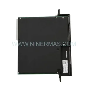
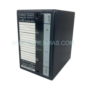
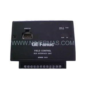
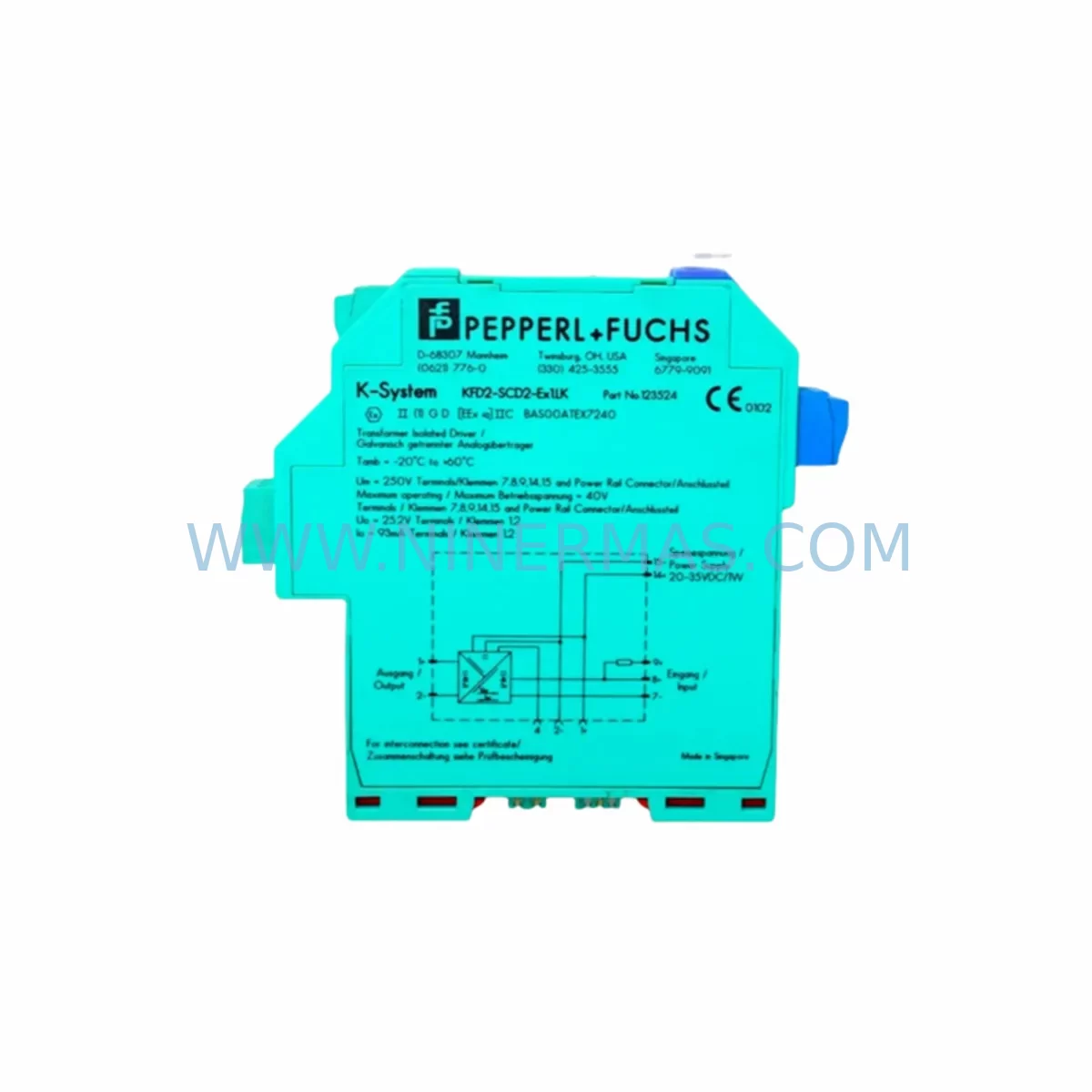
PEPPERL+FUCHS SCD2-STC-EX1 Retrofit-Compatible Transmitter Power Supply
Verify the part, confirm the platform family, and move straight into quotation with the right commercial details.
RFQ Ready
- SKUSCD2-STC-EX1
- CategoryPLC & Industrial Automation Modules
- BrandPepperl+Fuchs
- SupportAvailability, lead time, condition, and shipping coordination
How Buyers Usually Use This Page
- Confirm the exact part number and platform family before sending the quote request.
- Use direct email when quantity, condition, and destination are already defined internally.
- Switch to the broader brand or category archive when you need alternates nearby.
Series Navigation
Move through the most common platform families behind this part.
Product RFQ
Send this part directly for quotation.
Include quantity, required condition, destination country, and target delivery timing. Current reference: PEPPERL+FUCHS SCD2-STC-EX1 Retrofit-Compatible Transmitter Power Supply with SKU SCD2-STC-EX1.
PEPPERL+FUCHS SCD2-STC-EX1 Retrofit-Compatible Transmitter Power Supply for Legacy System Modernization
The PEPPERL+FUCHS SCD2-STC-EX1 is a field-proven transmitter power supply module designed for hazardous-area signal conditioning in process automation environments. As legacy DCS and PLC platforms approach end-of-life, the SCD2-STC-EX1 has become a critical retrofit component for engineers tasked with extending the operational life of existing control architectures without full system replacement. Its compact DIN-rail form factor, intrinsic safety barrier functionality, and compatibility with standard 4–20 mA HART transmitter loops make it a preferred choice for brownfield upgrade projects across oil and gas, chemical processing, and power generation facilities.
When planning a retrofit around the SCD2-STC-EX1, the first step is confirming the existing power supply rail capacity within the marshalling cabinet. The module draws from the 24 VDC bus, and engineers must verify that the existing PSU — often a legacy Pepperl+Fuchs KFD2-STC4-Ex1 or KFD2-STC4-Ex1.2O — can sustain the additional load after the swap. In many installations, the SCD2-STC-EX1 replaces older SCD series modules that have been discontinued, and the terminal wiring layout is largely preserved, reducing re-termination time significantly during planned shutdowns.
Field teams should pay close attention to the backplane slot assignment and module address configuration when integrating the SCD2-STC-EX1 into an existing Pepperl+Fuchs Remote I/O system such as the LB or FB series. The module’s channel addressing must align with the existing DCS tag database — typically managed through a Siemens S7-300 or S7-400 PLC, or a Honeywell Experion PKS controller — to avoid signal mapping errors that could trigger spurious alarms or process shutdowns. Where the original system used a KFD2-STC4-Ex1.2O with HART pass-through, the SCD2-STC-EX1 must be confirmed for equivalent HART communication support before the cutover.
Terminal block compatibility is another key verification point. The SCD2-STC-EX1 uses standard screw-clamp terminals compatible with 0.2–2.5 mm² conductors, consistent with most existing field cable cross-sections in legacy marshalling panels. If the original installation used Pepperl+Fuchs ZH-series zone barriers or KFA6-SR2-Ex2.W relay modules in the same cabinet, the SCD2-STC-EX1 can be installed in adjacent slots without requiring additional isolation measures, provided the hazardous-area classification (Zone 1 or Zone 2) is maintained.
For installations where the control system communicates via PROFIBUS DP or FOUNDATION Fieldbus H1, the SCD2-STC-EX1 retrofit must be coordinated with the segment coupler — typically a Pepperl+Fuchs DP/PA Coupler or an equivalent Siemens IM 153-2 interface module. Engineers should verify that the fieldbus segment load budget is not exceeded after adding the replacement module, and that the GSD file or device description (DD) file in the engineering workstation reflects the updated hardware configuration. HMI faceplate updates in the SCADA layer — whether running on Wonderware InTouch, Ignition, or a Siemens WinCC system — should be scheduled as part of the same maintenance window to maintain operator display consistency.
Installation space confirmation is essential before ordering. The SCD2-STC-EX1 occupies a standard 12.5 mm DIN-rail slot width. In densely populated marshalling cabinets, engineers should audit available rail space and verify that adjacent modules — such as Pepperl+Fuchs KFD2-UT2-Ex1 universal temperature converters or KFD2-CD-Ex1.32 current drivers — are not displaced during the swap. Where space is constrained, a phased replacement approach, replacing one channel group per maintenance window, is recommended to maintain partial system availability throughout the upgrade.
Pre-shipment testing is performed on every SCD2-STC-EX1 unit prior to dispatch. Each module is bench-tested under simulated 4–20 mA loop conditions, with HART communication verified at 1200 baud. Output linearity, input impedance, and intrinsic safety parameters are confirmed against the original Pepperl+Fuchs datasheet specifications. Units are shipped with a test report and are covered by a 12-month warranty from the date of delivery, supporting the spare parts lifecycle programs common in long-running process plant environments.
Upgrade Compatibility Table
| Parameter | SCD2-STC-EX1 (This Unit) | Typical Legacy Predecessor | Retrofit Notes |
|---|---|---|---|
| Form Factor | DIN-rail, 12.5 mm width | DIN-rail, 12.5 mm width | Direct slot replacement; no rail modification required |
| Supply Voltage | 24 VDC (via bus terminal) | 24 VDC | Verify PSU load capacity before installation |
| Signal Type | 4–20 mA HART | 4–20 mA (HART optional) | Confirm HART pass-through requirement with DCS engineer |
| Terminal Wiring | Screw-clamp, 0.2–2.5 mm² | Screw-clamp, 0.2–2.5 mm² | Existing field cables reusable; label and verify before cutover |
| Hazardous Area Rating | Zone 1 / Zone 2 (ATEX/IECEx) | Zone 1 / Zone 2 | Confirm area classification matches installation certificate |
| Communication Protocol | HART (4–20 mA loop) | HART / Analog | Update DD file in engineering workstation if HART is active |
| Module Address | Configurable via DIP switch | Fixed or DIP switch | Match original address to avoid DCS tag remapping |
| Commissioning | Loop calibration + HART verify | Loop calibration | Schedule within planned shutdown window; 30–60 min per channel |
| Warranty | 12-Month Warranty from date of delivery — covers manufacturing defects and functional failure under normal operating conditions | ||
Retrofit Planning for Existing Automation Systems
A successful SCD2-STC-EX1 retrofit begins with a thorough audit of the existing marshalling cabinet. Engineers should document every module currently installed in the affected DIN-rail segment, including adjacent Pepperl+Fuchs KFD2-STC4-Ex1.2O signal conditioners, KFD2-UT2-Ex1 temperature converters, and any KFD2-SR2-Ex2.W safety relays. This inventory forms the basis of the replacement bill of materials and ensures that the SCD2-STC-EX1 is ordered in the correct quantity to cover all affected channels in a single maintenance event.
Power distribution within the cabinet must be re-evaluated before the retrofit. If the existing 24 VDC bus is supplied by a legacy Pepperl+Fuchs KFD2-EB2 power bus module, the engineer should confirm that the bus current rating accommodates the SCD2-STC-EX1’s consumption alongside all other active modules. In larger cabinets with multiple DIN-rail segments, a Pepperl+Fuchs KFD2-EB2.R redundant power bus may already be in service; the SCD2-STC-EX1 is compatible with this configuration and does not require additional power conditioning.
Where the legacy system includes a Pepperl+Fuchs LB Remote I/O head station connected to a Siemens S7-400 via PROFIBUS DP, the SCD2-STC-EX1 replacement must be reflected in the hardware configuration within Siemens STEP 7 or TIA Portal. The GSD file for the updated module must be imported, and the slot assignment in the hardware catalog must match the physical installation. Failure to update the software configuration before restarting the PLC will result in a hardware fault alarm and potential process interruption.
For systems using a Yokogawa CENTUM VP or Honeywell Experion PKS as the primary DCS, the SCD2-STC-EX1 retrofit is typically transparent at the controller level, as the 4–20 mA signal interface remains unchanged. However, the HART device descriptor in the asset management system — such as Yokogawa PRM or Honeywell Asset Manager — should be updated to reflect the new module serial number and calibration date. This ensures that predictive maintenance schedules and instrument health monitoring remain accurate after the swap.
Field cable continuity testing using a Fluke 789 ProcessMeter or equivalent loop calibrator should be completed before the SCD2-STC-EX1 is powered up in the new installation. Each transmitter loop — whether a pressure transmitter, differential pressure cell, or temperature transmitter with a 4–20 mA output — should be verified for correct zero and span values after the module is installed. A programming cable connected to the HART handheld communicator (such as an Emerson 475 Field Communicator) allows in-situ verification of the transmitter configuration without removing the instrument from the process.
Downtime Control During System Migration
Minimizing downtime during an SCD2-STC-EX1 retrofit requires a structured cutover plan developed in advance of the maintenance window. The recommended approach is a channel-by-channel replacement strategy: each transmitter loop is isolated, the legacy module is removed, the SCD2-STC-EX1 is installed and wired, and the loop is re-commissioned before moving to the next channel. This approach limits the number of open loops at any given time and reduces the risk of a process upset caused by simultaneous loss of multiple measurement points.
Before the cutover begins, the DCS operator should place all affected control loops in manual mode and confirm that the process is in a stable, safe state. The original program logic — including PID tuning parameters, alarm setpoints, and interlock conditions — should be exported from the controller and archived as a backup. For Siemens S7 systems, this means saving the current DB and FC blocks from STEP 7 or TIA Portal. For Honeywell Experion systems, the control module configuration should be exported via Control Builder before any hardware changes are made.
Where the process cannot tolerate a full loop outage, a temporary bypass using a portable signal generator — such as a Beamex MC6 or equivalent — can maintain a simulated 4–20 mA signal to the DCS input while the SCD2-STC-EX1 is being installed. This technique is particularly useful in continuous process plants where flow or pressure measurements feed critical safety interlocks. Once the new module is installed and the field transmitter loop is restored, the bypass is removed and the loop is returned to automatic control.
Post-installation verification should include a full loop check from the field transmitter to the DCS historian, confirming that the engineering unit conversion, alarm limits, and trend display in the HMI are consistent with the pre-retrofit configuration. Any discrepancies in the SCADA display — such as incorrect tag scaling or missing HART device information — should be resolved before the maintenance window is closed and the loop is returned to automatic operation. All retrofit activities should be documented in the plant’s maintenance management system (CMMS) with the SCD2-STC-EX1 serial number, installation date, and calibration records attached.
Retrofit Support FAQ
Q1: Is the SCD2-STC-EX1 a direct drop-in replacement for the legacy SCD series transmitter power supply modules?
In most installations, yes. The SCD2-STC-EX1 shares the same 12.5 mm DIN-rail footprint and 24 VDC bus supply as the legacy SCD series, and the terminal wiring layout is compatible with standard field cable configurations. Engineers should verify the HART communication requirement and module address assignment before completing the swap, as these parameters may differ between the original and replacement units depending on the DCS configuration.
Q2: What commissioning steps are required after installing the SCD2-STC-EX1?
After installation, the following steps are recommended: (1) Verify terminal wiring continuity with a loop calibrator; (2) Power up the module and confirm the 24 VDC bus voltage at the module terminals; (3) Perform a loop calibration from 4 mA (0%) to 20 mA (100%) and verify the DCS input reading; (4) If HART is active, connect a HART communicator and confirm device identification and PV reading; (5) Return the control loop to automatic mode and monitor for 15–30 minutes to confirm stable operation.
Q3: Is stock available for immediate shipment, and what is the lead time for larger quantities?
Stock availability for the SCD2-STC-EX1 is maintained to support urgent retrofit and breakdown replacement requirements. Standard orders are typically dispatched within 3–5 business days after order confirmation. For larger quantities required for planned shutdown projects, we recommend contacting our sales team at sale@ninermas.com to confirm stock levels and arrange a dedicated supply commitment. Long-term spare parts programs with fixed lead times are available for customers with ongoing lifecycle management requirements.
Q4: What does the 12-month warranty cover, and how is a warranty claim processed?
The 12-month warranty covers manufacturing defects and functional failure under normal operating conditions from the date of delivery. Each unit is pre-shipment tested and dispatched with a test report. In the event of a warranty claim, the defective unit should be returned with the original test report and a description of the failure mode. Replacement units are dispatched within 5 business days of receiving the returned module. The warranty does not cover damage caused by incorrect installation, overvoltage, or operation outside the specified environmental conditions.
| Product Series | Other series |
|---|---|
| Country of Origin | DE |
Catalog Continuation
More Pepperl+Fuchs modules in the catalog.
Use the brand lane to compare nearby part numbers, platform-adjacent modules, and other inquiry-ready listings before sending your final RFQ.
SKU: MB-16U5L-103681 MB-C3-DI32-AKB-131969
Pepperl+Fuchs MB-16U5L-103681 Safety-Reliable DI Module for Critical Control Sites
SKU: KFD2-STC5-EX1
Pepperl+Fuchs KFD2-STC5-EX1 Retrofit Signal Conditioner
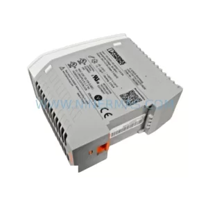
SKU: P+F PS2500/PM-115 Power Supply Model
Pepperl+Fuchs PS2500/PM-115 Safety-Reliable Power Supply
Catalog Continuation
Alternative parts within PLC & Industrial Automation Modules.
Stay inside the same system family when you need substitutes, adjacent modules, or a broader shortlist for procurement review.
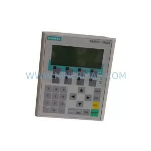
SKU: 6AV6641-0CA01-0AX1
Siemens 6AV6641-0CA01-0AX1 Service-Ready Spare Part for Industrial Maintenance
SKU: VT-VSPA1-1-11
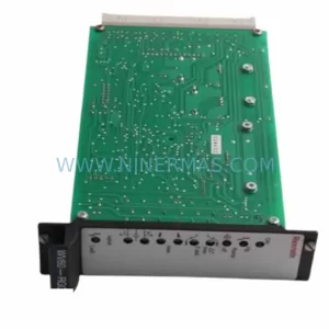
Rexroth VT-VSPA1-1-11 Retrofit-Compatible Valve Amplifier