Original Industrial Spare Part
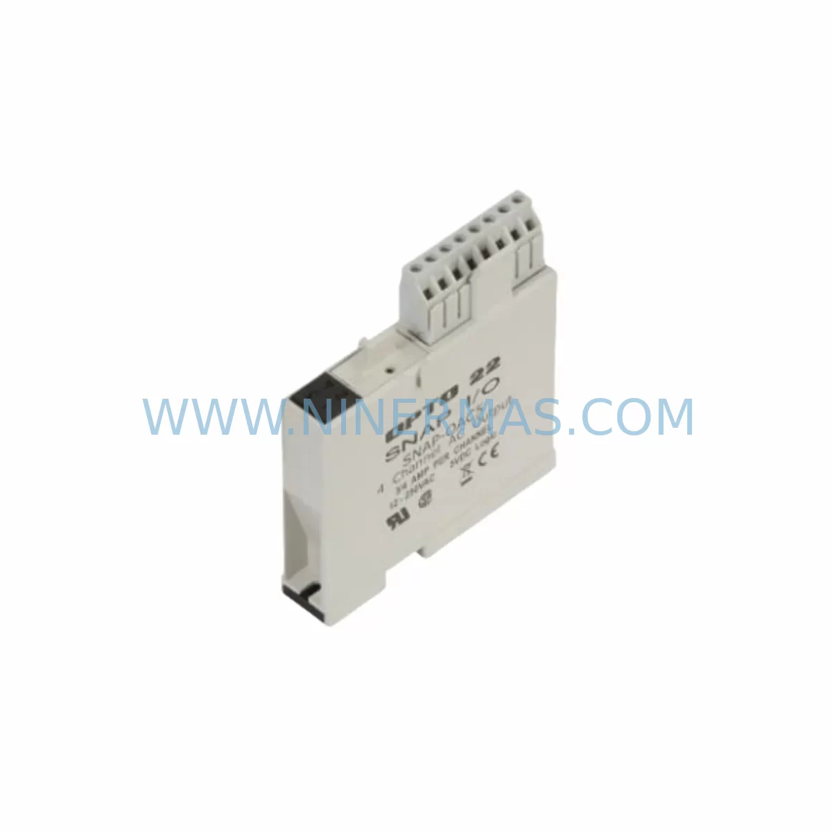
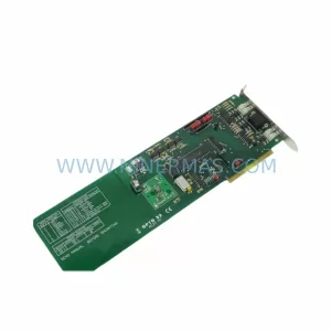
OPTO 22 SNAP-LCSX-PLUS Retrofit-Compatible Brain for Legacy Systems
Verify the part, confirm the platform family, and move straight into quotation with the right commercial details.
RFQ Ready
- SKUSNAP-LCSX-PLUS
- CategoryPLC & Industrial Automation Modules
- BrandOPTO 22
- SupportAvailability, lead time, condition, and shipping coordination
How Buyers Usually Use This Page
- Confirm the exact part number and platform family before sending the quote request.
- Use direct email when quantity, condition, and destination are already defined internally.
- Switch to the broader brand or category archive when you need alternates nearby.
Series Navigation
Move through the most common platform families behind this part.
Product RFQ
Send this part directly for quotation.
Include quantity, required condition, destination country, and target delivery timing. Current reference: OPTO 22 SNAP-LCSX-PLUS Retrofit-Compatible Brain for Legacy Systems with SKU SNAP-LCSX-PLUS.
OPTO 22 SNAP-LCSX-PLUS Retrofit-Compatible Brain for Legacy Systems: Seamless Upgrade for Aging SNAP Automation Platforms
The OPTO 22 SNAP-LCSX-PLUS is a high-performance programmable brain module designed for the SNAP Series distributed I/O platform. As industrial facilities face increasing pressure to modernize aging control infrastructure without full system replacement, the SNAP-LCSX-PLUS has become a critical retrofit component for engineers managing legacy SNAP racks, end-of-life controllers, and discontinued automation hardware. With native Ethernet connectivity, onboard processing capability, and full compatibility with the SNAP I/O backplane ecosystem, this module enables a controlled, low-risk migration path from obsolete control architectures to modern, networked automation environments.
Whether you are replacing a failed SNAP-LCE or SNAP-LCX brain, upgrading a SNAP-B3 or SNAP-B6 rack to support expanded I/O addressing, or migrating from a legacy serial-based control network to Ethernet/IP or Modbus TCP, the SNAP-LCSX-PLUS provides the processing headroom and protocol flexibility required for a smooth transition. Its compatibility with existing SNAP analog and digital I/O modules — including SNAP-IAC-5, SNAP-ODC5, SNAP-AIMA-4, and SNAP-AOVA-4 — means that field wiring, terminal blocks, and I/O module assignments can typically be preserved during the upgrade, dramatically reducing rewiring labor and downtime exposure.
Upgrade Compatibility Table
| Parameter | SNAP-LCSX-PLUS | Legacy SNAP-LCE / SNAP-LCX |
|---|---|---|
| Communication Interface | 10/100 Ethernet (RJ-45) | Serial RS-232 / RS-485 (varies) |
| Supported Protocols | Modbus TCP, EtherNet/IP, SNMP, HTTP | Modbus RTU, proprietary serial |
| Backplane Compatibility | SNAP-B3, SNAP-B6, SNAP-B10, SNAP-B16 | Same SNAP backplane family |
| I/O Module Compatibility | Full SNAP analog and digital I/O range | Partial — limited by firmware version |
| Programming Environment | PAC Control, PAC Manager | ioControl (legacy), limited PAC support |
| Onboard Memory | Expanded flash and RAM | Limited — no strategy persistence |
| Installation Form Factor | Direct SNAP rack mount, same footprint | Same rack mount |
| Retrofit Recommendation | Recommended drop-in upgrade | End-of-life, no longer manufactured |
| Commissioning Requirement | IP assignment, strategy download, I/O map verification | COM port configuration, address DIP switches |
| Warranty | 12-Month Warranty (NINERMAS) | No warranty — discontinued |
Retrofit Planning for Existing Automation Systems
A successful SNAP-LCSX-PLUS retrofit begins well before the module arrives on site. Engineers should start by auditing the existing SNAP rack configuration — identifying the backplane model (SNAP-B3, SNAP-B6, SNAP-B10, or SNAP-B16), cataloging all installed I/O modules by slot position, and documenting the current I/O map as defined in the legacy ioControl or PAC Control strategy. This documentation becomes the baseline for verifying that the new SNAP-LCSX-PLUS strategy replicates all point addresses, scaling parameters, and alarm thresholds without deviation.
Power supply capacity is a critical pre-retrofit checkpoint. The SNAP-LCSX-PLUS draws its logic power from the SNAP-PS5 or SNAP-PS24 power supply mounted on the rack. Before installation, confirm that the existing power supply can support the combined load of the brain module and all installed I/O modules. If the rack is fully populated with high-density analog modules such as SNAP-AIMA-4 or SNAP-AOVA-4, a power budget calculation is essential. In some cases, a power supply upgrade or the addition of a secondary SNAP-PS5 may be required before the brain swap can proceed safely.
Terminal wiring and field device connections are generally preserved during a SNAP-LCSX-PLUS retrofit, since the I/O modules themselves remain in place. However, engineers should verify that all SNAP digital input modules (such as SNAP-IDC5 or SNAP-IAC-5) and digital output modules (such as SNAP-ODC5 or SNAP-OAC5) are seated correctly and that terminal block torque specifications are met after any rack disturbance. For analog signal chains, confirm that 4–20 mA loop wiring and shielding practices remain intact, particularly for SNAP-AIMA-4 current input modules connected to field transmitters.
Communication architecture planning is equally important. The SNAP-LCSX-PLUS communicates over Ethernet, which means the retrofit may require running a new Cat5e or Cat6 cable from the control cabinet to the plant network switch, assigning a static IP address, and configuring the subnet mask and gateway to match the facility’s network topology. If the legacy system used a SNAP-LCE with RS-232 serial communication to a host SCADA or DCS, the migration to Ethernet/IP or Modbus TCP will require corresponding updates to the SCADA driver configuration and tag database. HMI screens connected to the legacy brain via serial polling will need to be reconfigured to use the new Ethernet-based communication path, and all animated display elements should be tested against live I/O before the system is returned to production.
For facilities running OPTO 22 PAC Display or third-party HMI platforms, the tag remapping process should be completed and validated in a staging environment before the cutover window. Any custom PAC Control flowchart strategies should be exported from the legacy brain (if still functional) and re-downloaded to the SNAP-LCSX-PLUS after IP configuration. If the legacy brain is non-functional, the strategy must be reconstructed from the most recent backup or from the original engineering documentation.
Downtime Control During System Migration
Minimizing unplanned downtime is the primary operational concern during any SNAP-LCSX-PLUS retrofit. The recommended approach is to pre-configure the new brain module off-line before the scheduled maintenance window. Using PAC Manager, assign the target IP address, download the verified PAC Control strategy, and confirm that all I/O point definitions match the existing rack configuration. This pre-commissioning step eliminates the most time-consuming tasks from the live cutover window and reduces the on-site swap to a physical module exchange followed by a brief I/O verification sequence.
During the cutover, follow a structured isolation procedure: notify the operations team, place the process in manual or safe state, de-energize the rack power supply, remove the legacy brain module, install the SNAP-LCSX-PLUS in the same slot, restore power, and verify Ethernet link establishment. Once the brain is online, use PAC Manager to confirm that all I/O modules are recognized and that point values are reading correctly before transferring control back to automatic mode. The entire physical swap and initial verification can typically be completed within 15 to 30 minutes when the module has been pre-configured.
To protect the original program logic, always maintain a version-controlled backup of the PAC Control strategy file (.PAC) before initiating any retrofit. Store backups in a secure, off-site location and document the strategy version, I/O map revision, and firmware version of the outgoing brain module. This documentation supports both the commissioning verification process and any future audit or compliance review. For critical production lines where even brief interruptions carry significant cost, consider staging a fully pre-configured SNAP-LCSX-PLUS as a hot spare, ready for immediate deployment in the event of an unplanned brain failure.
Retrofit Support FAQ
Q1: Is the SNAP-LCSX-PLUS a direct drop-in replacement for the SNAP-LCE or SNAP-LCX?
Yes. The SNAP-LCSX-PLUS uses the same SNAP rack mounting interface and backplane connector as the SNAP-LCE and SNAP-LCX, making it physically compatible with all standard SNAP backplanes including the SNAP-B3, SNAP-B6, SNAP-B10, and SNAP-B16. The primary difference is the communication interface: the SNAP-LCSX-PLUS uses Ethernet rather than serial, so network cabling and IP configuration are required. The PAC Control strategy must also be re-downloaded to the new brain after installation.
Q2: What commissioning steps are required after installing the SNAP-LCSX-PLUS?
After physical installation, use PAC Manager to assign a static IP address to the brain. Download the verified PAC Control strategy via Ethernet. Confirm that all I/O modules are recognized in the I/O unit configuration. Verify that analog input scaling, digital output states, and alarm setpoints match the pre-retrofit baseline. Test all critical control loops in manual mode before returning the system to automatic operation. Document the firmware version and strategy revision for the commissioning record.
Q3: Can the SNAP-LCSX-PLUS communicate with existing SCADA systems that used serial Modbus RTU with the legacy brain?
The SNAP-LCSX-PLUS supports Modbus TCP over Ethernet, not Modbus RTU over serial. If your SCADA system currently uses a serial Modbus RTU driver to communicate with the legacy brain, you will need to update the SCADA communication driver to Modbus TCP and configure the correct IP address and port. Most modern SCADA platforms support Modbus TCP natively. If your SCADA system does not support Modbus TCP, a serial-to-Ethernet converter or protocol gateway can be used as an interim solution.
Q4: What warranty and supply assurance does NINERMAS provide for the SNAP-LCSX-PLUS?
All SNAP-LCSX-PLUS units supplied by NINERMAS are covered by a 12-month warranty against manufacturing defects and functional failure under normal operating conditions. Each unit undergoes pre-shipment functional testing to verify Ethernet communication, I/O backplane interface, and strategy download capability before dispatch. NINERMAS maintains inventory stock of the SNAP-LCSX-PLUS and related SNAP Series components to support urgent retrofit and emergency replacement requirements. For stock availability, lead time confirmation, or volume pricing, contact sale@ninermas.com or call +0086 187 5021 5667.
| Product Series | Legacy |
|---|
Catalog Continuation
More OPTO 22 modules in the catalog.
Use the brand lane to compare nearby part numbers, platform-adjacent modules, and other inquiry-ready listings before sending your final RFQ.
Catalog Continuation
Alternative parts within PLC & Industrial Automation Modules.
Stay inside the same system family when you need substitutes, adjacent modules, or a broader shortlist for procurement review.
SKU: SCE906A2-002-01 SCE906A200201
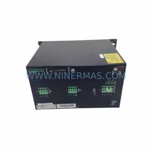
Pacific Scientific SCE906A2-002-01 Retrofit Servo Amplifier
SKU: EPC500 3183062451
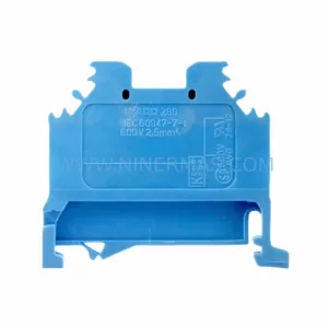
Alfa Laval EPC500 3183062451 Service-Ready Spare Part