Original Industrial Spare Part
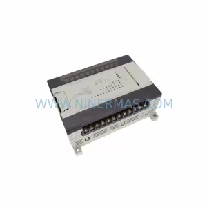
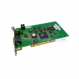
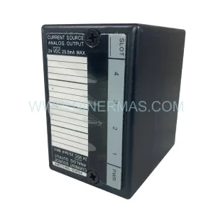
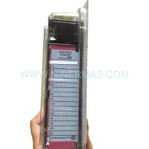
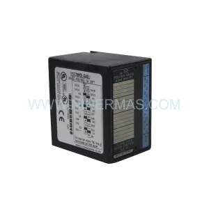
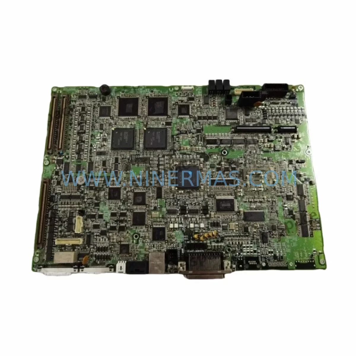
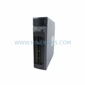
Mitsubishi YZ311B BU778A011G53A Retrofit-Compatible Drive for Legacy Systems
Verify the part, confirm the platform family, and move straight into quotation with the right commercial details.
RFQ Ready
- SKUYZ311B BU778A011G53A
- CategoryPLC & Industrial Automation Modules
- BrandMitsubishi
- SupportAvailability, lead time, condition, and shipping coordination
How Buyers Usually Use This Page
- Confirm the exact part number and platform family before sending the quote request.
- Use direct email when quantity, condition, and destination are already defined internally.
- Switch to the broader brand or category archive when you need alternates nearby.
Series Navigation
Move through the most common platform families behind this part.
Product RFQ
Send this part directly for quotation.
Include quantity, required condition, destination country, and target delivery timing. Current reference: Mitsubishi YZ311B BU778A011G53A Retrofit-Compatible Drive for Legacy Systems with SKU YZ311B BU778A011G53A.
Mitsubishi YZ311B BU778A011G53A Retrofit-Compatible Drive for Legacy Systems
The Mitsubishi YZ311B BU778A011G53A is a servo drive unit originally developed for the MELSERVO series, widely deployed across legacy CNC machining centers, automated assembly lines, and precision motion control cabinets. As original equipment reaches end-of-life and OEM supply channels close, plant engineers and maintenance teams increasingly rely on verified retrofit-compatible replacements to sustain production continuity without committing to full system overhauls. This unit addresses exactly that need — providing a mechanically and electrically compatible replacement path for aging MELSERVO-based control architectures.
Whether you are managing a scheduled retrofit during a planned maintenance window or responding to an unplanned drive failure, the YZ311B BU778A011G53A is stocked and available for immediate dispatch. Each unit undergoes pre-shipment functional testing and is covered by a 12-month warranty from the date of delivery, giving procurement and engineering teams the confidence to proceed without extended qualification cycles.
Upgrade Compatibility Table
| Parameter | Details |
|---|---|
| SKU / Part Number | YZ311B BU778A011G53A |
| Brand / Series | Mitsubishi / MELSERVO |
| Unit Type | Servo Drive / Amplifier Unit |
| Mounting Interface | Backplane / rack-mount compatible with MELSERVO drive cabinets |
| Communication Compatibility | SSCNET / RS-422 serial (verify against host controller revision) |
| Power Supply Requirement | Confirm input voltage rating against existing cabinet power module (e.g., MR-PWS1CBL03M-A2 or equivalent) |
| Terminal Wiring | CN1 / CN2 / CN3 connector pinout — verify against original wiring diagram before installation |
| Module Address Setting | Rotary switch or DIP configuration — confirm axis address matches original drive assignment |
| Program Compatibility | Servo parameters stored in host controller (MR Configurator2 or GX Works2 recommended for parameter backup) |
| HMI Screen Mapping | Verify GOT2000 or GT Designer3 screen tags reference correct axis device addresses post-swap |
| Installation Clearance | Confirm rack slot width and depth against cabinet layout drawing |
| Replacement Recommendation | Direct retrofit replacement for equivalent MELSERVO-J2S / J3 series drive units |
| Pre-Shipment Testing | Functional load test performed on each unit prior to dispatch |
| Warranty | 12 months from date of delivery |
Retrofit Planning for Existing Automation Systems
Successful integration of the YZ311B BU778A011G53A into an existing control cabinet begins well before the physical swap. Engineers should start by auditing the full drive cabinet layout, identifying the host controller — typically a Mitsubishi MELSEC Q-series or iQ-R series PLC — and confirming the servo network topology. In SSCNET III/H architectures, the optical fiber link between the controller and each MR-J4 or MR-J3 amplifier must be accounted for, and the replacement drive must be confirmed compatible with the installed servo amplifier generation.
Terminal wiring is a critical checkpoint. The CN1 encoder feedback connector, CN2 I/O signal connector, and CN3 battery connector must be mapped against the original wiring diagram. Any deviation in pinout between the legacy unit and the replacement — particularly on the encoder differential signal lines — can result in encoder fault alarms (AL.16, AL.17) immediately upon power-up. Having the original wiring diagram and the replacement unit’s technical datasheet available side-by-side during installation is strongly recommended.
Power capacity verification is equally important. The servo drive cabinet typically houses a dedicated power supply module — such as an MR-PWS1CBL or equivalent regenerative resistor unit — and the total rated output current must accommodate the replacement drive’s peak demand. If the existing power module is already operating near capacity due to multi-axis configurations, a power budget recalculation is necessary before commissioning.
For systems using a GOT2000 series HMI or an older GT1000 panel, screen tag assignments referencing axis device words (e.g., D registers or special relay M codes) must be verified after the drive swap. If the replacement drive is assigned a different axis number or if the servo parameter file has been updated, HMI screen logic may require corresponding adjustments in GT Designer3 to maintain accurate status display and alarm visualization.
I/O expansion modules connected via MELSEC CC-Link or CC-Link IE Field should also be reviewed. If the retrofit involves reconfiguring the servo axis count or remapping I/O points, the CC-Link station address assignments and the GX Works2 network parameter file must be updated accordingly. Failure to synchronize these settings can result in communication timeout errors (CC-Link error code 7000 or similar) that halt the entire production line.
Backplane slot assignment is another area requiring careful attention. In multi-axis MELSERVO cabinets, each drive occupies a defined slot position that corresponds to its axis address in the servo program. Inserting the replacement unit into the wrong slot — or failing to set the axis address rotary switch to match the original — will cause the host controller to report a servo axis configuration mismatch at startup. Always photograph the original slot layout and switch settings before removing the legacy unit.
Programming cable access is often overlooked during retrofit planning. Having a MR-J3USBCBL3M USB programming cable or equivalent on-site allows direct parameter verification via MR Configurator2 without requiring the host PLC to be online. This is particularly valuable when the original servo parameter file is unavailable and parameters must be reconstructed from the motor nameplate data and application specifications.
Signal isolators may be required if the replacement drive’s analog input impedance differs from the legacy unit, particularly in tension control or speed reference applications where a ±10V analog command signal is sourced from a third-party controller. A DIN-rail mounted signal conditioner can bridge impedance mismatches and protect the drive’s analog input stage from ground loop interference common in older cabinet wiring.
Downtime Control During System Migration
Minimizing production downtime during a servo drive replacement requires a structured pre-outage preparation protocol. Before the maintenance window opens, the servo parameter file should be backed up from the host controller using GX Works2 or MR Configurator2 and stored on a local engineering laptop as well as a network share. The original PLC program — including all motion control routines, home position logic, and safety interlock sequences — should be archived and version-tagged to prevent accidental overwrite during the retrofit.
During the physical swap, the recommended sequence is: de-energize the cabinet following LOTO (Lockout/Tagout) procedures, photograph all connector positions and cable routing, remove the legacy drive, install the YZ311B BU778A011G53A into the same slot, reconnect all connectors in reverse order, and verify torque on terminal block screws before re-energizing. The entire mechanical swap can typically be completed within 30 to 45 minutes by a trained technician familiar with MELSERVO cabinet layouts.
Upon power restoration, the host controller should be brought online in monitor mode before enabling servo axes. This allows the engineer to confirm that the servo amplifier is recognized on the network, that no axis configuration alarms are present, and that encoder feedback is being received correctly. Only after all axes report ready status should the machine be returned to automatic cycle mode.
For critical production lines where even a brief unplanned outage carries significant cost, maintaining a pre-tested spare unit of the YZ311B BU778A011G53A in the local spare parts cabinet is the most effective downtime mitigation strategy. Combined with a documented retrofit procedure specific to the machine, this approach reduces mean time to repair (MTTR) to under one hour in most scenarios.
Retrofit Support FAQ
Q1: Is the YZ311B BU778A011G53A a direct drop-in replacement for the original MELSERVO unit?
A: The YZ311B BU778A011G53A is designed as a retrofit-compatible replacement for equivalent MELSERVO-J2S and J3 series servo drive units. Connector positions, mounting dimensions, and communication interfaces are compatible with the original cabinet design. However, engineers should verify the axis address switch setting and confirm servo parameters are correctly loaded before returning the machine to production.
Q2: What commissioning steps are required after installation?
A: After physical installation, connect the programming cable and use MR Configurator2 to verify or restore servo parameters. Confirm encoder feedback (AL.16/AL.17 absence), check axis address assignment, perform a JOG operation at low speed to verify motor rotation direction, and run a homing cycle before enabling automatic operation. Document all parameter values post-commissioning for future reference.
Q3: How is wiring compatibility confirmed before installation?
A: Compare the CN1, CN2, and CN3 connector pinouts from the replacement unit’s technical datasheet against the original wiring diagram. Pay particular attention to encoder signal lines (A+, A−, B+, B−, Z+, Z−), the servo-on (SON) input, and the alarm output (ALM) signal. If the original wiring diagram is unavailable, the cabinet wiring can be traced and documented before the legacy unit is removed.
Q4: What does the 12-month warranty cover, and what is the stock availability?
A: Each YZ311B BU778A011G53A unit is covered by a 12-month warranty from the date of delivery, covering manufacturing defects and functional failures under normal operating conditions. Units are stocked and available for immediate dispatch. Pre-shipment functional testing is performed on every unit. For volume orders or scheduled maintenance programs requiring multiple units, contact our sales team to confirm lead times and reserve stock allocation.
| Product Series | Legacy |
|---|---|
| Country of Origin | JP |
Catalog Continuation
More Mitsubishi modules in the catalog.
Use the brand lane to compare nearby part numbers, platform-adjacent modules, and other inquiry-ready listings before sending your final RFQ.
Catalog Continuation
Alternative parts within PLC & Industrial Automation Modules.
Stay inside the same system family when you need substitutes, adjacent modules, or a broader shortlist for procurement review.