Original Industrial Spare Part
Mitsubishi AY41 Retrofit-Compatible Digital Output Module
Verify the part, confirm the platform family, and move straight into quotation with the right commercial details.
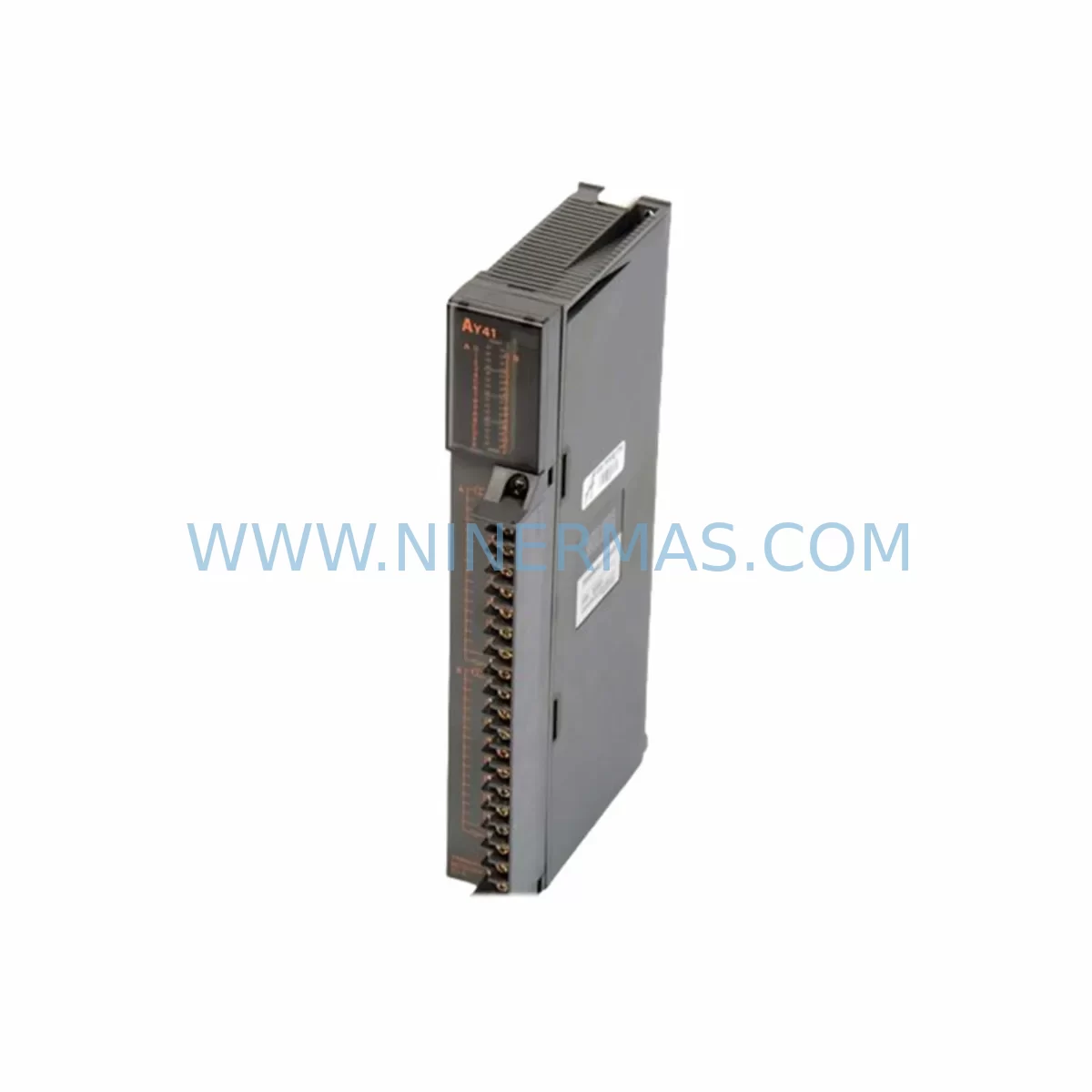
RFQ Ready
- SKUAY41
- CategoryPLC & Industrial Automation Modules
- BrandMitsubishi
- SupportAvailability, lead time, condition, and shipping coordination
How Buyers Usually Use This Page
- Confirm the exact part number and platform family before sending the quote request.
- Use direct email when quantity, condition, and destination are already defined internally.
- Switch to the broader brand or category archive when you need alternates nearby.
Series Navigation
Move through the most common platform families behind this part.
Product RFQ
Send this part directly for quotation.
Include quantity, required condition, destination country, and target delivery timing. Current reference: Mitsubishi AY41 Retrofit-Compatible Digital Output Module with SKU AY41.
Mitsubishi AY41 Retrofit-Compatible Digital Output Module for Legacy Systems
The Mitsubishi AY41 is a transistor-type digital output local unit module designed for the MELSEC A-series programmable logic controller platform. As legacy automation systems approach end-of-life, the AY41 remains a critical spare part and retrofit component for engineers managing aging production lines, control cabinets, and distributed I/O architectures. Whether you are replacing a failed output module, upgrading a legacy control panel, or migrating from an obsolete A-series rack to a modern Q-series or iQ-R platform, the AY41 provides a reliable, field-proven solution that minimizes downtime and preserves existing wiring infrastructure.
The AY41 delivers 16-point transistor output with a rated load voltage of 12–24 VDC and a maximum load current of 0.5 A per point. Its compact form factor is designed to fit directly into A-series base units and extension base units, including the A1S series racks. When sourcing this module for retrofit applications, engineers must verify the base unit slot count, power supply capacity, and I/O address allocation before installation. The AY41 occupies a standard slot on the A-series backplane and communicates with the CPU module — such as the A2UCPU, A3UCPU, or A2SHCPU — through the internal bus, requiring no additional communication configuration beyond the standard I/O parameter settings in GX Developer or GX Works2.
For facilities running legacy MELSEC A-series systems, the AY41 is frequently paired with companion modules including the AX40 and AX80 digital input modules, the AD61 analog input module, and the A1SD61 high-speed counter module. In control cabinets where the A-series rack is mounted alongside an A1S61PN or A1S62PN power supply module, engineers should confirm that the total current draw of all installed I/O modules — including the AY41 — does not exceed the rated output capacity of the power supply. Overloading the backplane power rail is a common cause of intermittent faults during retrofit commissioning.
Upgrade Compatibility Table
| Parameter | AY41 (Legacy) | Retrofit / Upgrade Notes |
|---|---|---|
| Output Type | Transistor (Sink) | Verify field device polarity before wiring |
| Output Points | 16 points | Map I/O addresses in GX Developer / GX Works2 |
| Rated Load Voltage | 12–24 VDC | Confirm field device voltage compatibility |
| Max Load Current | 0.5 A / point | Check total current vs. power supply rating |
| Backplane Interface | A-series bus connector | Not directly compatible with Q-series base units |
| Compatible Racks | A1S, A2, A3 base units | Confirm slot availability and rack model |
| Compatible CPUs | A2UCPU, A3UCPU, A2SHCPU | Verify firmware version for I/O recognition |
| Communication Protocol | Internal A-series bus | No additional comm module required for local I/O |
| Programming Tool | GX Developer / GX Works2 | Ladder logic reuse possible with minor I/O remapping |
| Installation Space | Standard A-series slot | Confirm physical slot clearance in cabinet |
| Warranty | 12-Month Warranty — Pre-shipment tested, documented QA | |
Retrofit Planning for Existing Automation Systems
When integrating the AY41 into an existing retrofit project, the planning phase must address several interdependent system elements. Begin by auditing the current A-series rack configuration: identify the base unit model, the number of occupied slots, and the current power budget. If the rack is an A1S series unit, the A1S61PN power supply module typically provides 5 VDC at 3 A for the backplane. Adding or replacing an AY41 in a fully loaded rack may require redistributing modules or upgrading to a higher-capacity power supply such as the A1S62PN.
Terminal wiring is the next critical checkpoint. The AY41 uses a 40-pin connector with a standard A-series terminal assignment. When replacing a failed AY41, engineers should photograph or document the existing wiring before disconnection. Field devices connected to the output terminals — including solenoid valves, relay coils, indicator lamps, and motor starters — must be verified against the 0.5 A per-point current limit. Inductive loads require suppression diodes or RC snubber circuits to prevent voltage spikes that can damage the transistor output stage.
For systems where the A-series CPU is being retained but the I/O modules are being refreshed, the AY41 can be replaced on a one-for-one basis without modifying the existing ladder program, provided the I/O address assignment remains unchanged. This is a significant advantage in retrofit scenarios where reprogramming the CPU — such as an A2SHCPU or A3UCPU — would require re-validation of the entire control sequence. In contrast, if the retrofit involves migrating to a Q-series platform using a QnA-compatible CPU such as the Q02CPU, engineers must use the A/QnA conversion adapter or redesign the I/O wiring to match Q-series module pinouts.
Communication architecture is another consideration in multi-rack or distributed systems. If the AY41 is installed in an extension base unit connected to the main rack via an A1SC07B or A1SC12B extension cable, the cable integrity and termination resistance must be verified before powering up the system. Signal degradation on extension cables is a common source of intermittent I/O faults in aging installations. In systems where the A-series rack communicates upstream to a SCADA or DCS via an A1SJ71UC24-R2 serial communication module or an A1SJ71E71-B2 Ethernet module, the communication parameters — baud rate, station number, and protocol — must be preserved during the module swap to avoid disrupting the supervisory link.
HMI screens connected to the A-series CPU via RS-232 or RS-422 — including legacy GOT900 or GOT1000 series panels — typically reference I/O bit addresses directly. If the AY41 replacement results in any I/O address shift, the HMI screen data must be updated accordingly using GT Designer2 or GT Designer3. Failure to synchronize HMI address maps with the updated I/O configuration is a frequent cause of post-retrofit alarm and interlock failures.
Downtime Control During System Migration
Minimizing production downtime during an AY41 replacement or A-series retrofit requires a structured pre-outage preparation protocol. Before the maintenance window opens, the engineering team should complete a full backup of the CPU program using GX Developer or GX Works2, export the current I/O parameter file, and document all active output states from the HMI or SCADA historian. This baseline record allows rapid restoration if the replacement module does not initialize correctly.
During the outage, the recommended sequence is: de-energize the control cabinet, discharge any capacitive loads on the output terminals, remove the failed AY41, inspect the backplane connector for bent pins or contamination, install the replacement module, and restore power in stages — first the backplane power supply, then the CPU, and finally the I/O modules. The CPU should be placed in STOP mode during module installation to prevent unintended output activation. After power restoration, verify that the AY41 RUN LED illuminates and that no ERR LED is active on the CPU or the module itself.
For planned migrations from A-series to Q-series platforms, a phased approach is strongly recommended. Retain the existing A-series rack in parallel with the new Q-series rack during the transition period, using an A1SJ71QLP21 MELSECNET/10 link module or a direct I/O handoff strategy to maintain control continuity. This parallel-run approach allows the engineering team to validate the new Q-series program — including QY41P or QY50 output modules — against the original A-series logic before committing to a full cutover. The result is a controlled migration that protects production continuity and reduces the risk of undetected logic errors reaching the field.
Retrofit Support FAQ
Q1: Is the AY41 a direct drop-in replacement for a failed unit in an A1S-series rack?
Yes. The AY41 is designed for A-series and A1S-series base units and can be replaced on a one-for-one basis without modifying the CPU program, provided the I/O address assignment and wiring remain unchanged. Confirm the slot position and terminal wiring before installation.
Q2: What pre-shipment testing is performed on the AY41?
Each AY41 unit supplied by NINERMAS undergoes functional output verification, backplane connector inspection, and load current testing prior to shipment. A test report is available upon request. All units are covered by a 12-month warranty from the date of shipment.
Q3: Can the AY41 be used in a system migrating from A-series to Q-series?
The AY41 is not directly compatible with Q-series base units due to the difference in backplane bus architecture. For Q-series migrations, equivalent output modules such as the QY41P or QY50 should be specified. The AY41 can continue to serve in the legacy A-series rack during a phased migration period.
Q4: What is the lead time and stock availability for the AY41?
NINERMAS maintains in-stock inventory of the AY41 to support urgent retrofit and breakdown replacement requirements. Standard lead time for in-stock units is 3–5 business days for international shipment. For long-term supply commitments or bulk orders supporting lifecycle extension programs, please contact our sales team directly.
| Product Series | MELSEC |
|---|---|
| Country of Origin | JP |
Catalog Continuation
More Mitsubishi modules in the catalog.
Use the brand lane to compare nearby part numbers, platform-adjacent modules, and other inquiry-ready listings before sending your final RFQ.
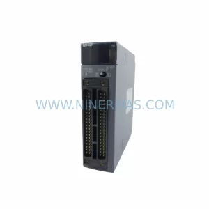
Catalog Continuation
Alternative parts within PLC & Industrial Automation Modules.
Stay inside the same system family when you need substitutes, adjacent modules, or a broader shortlist for procurement review.
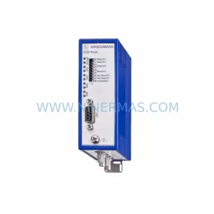
SKU: OZDPROFI12MG12
Hirschmann OZDPROFI12MG12 Spare Part for Industrial Maintenance
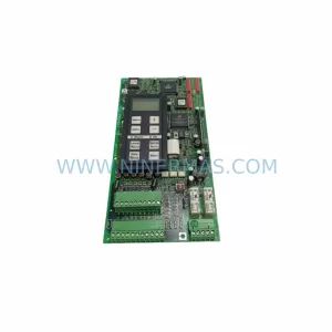
SKU: 07025-0000-70-1-04
KONTRON 07025-0000-70-1-04 Service-Ready Spare Part