Original Industrial Spare Part
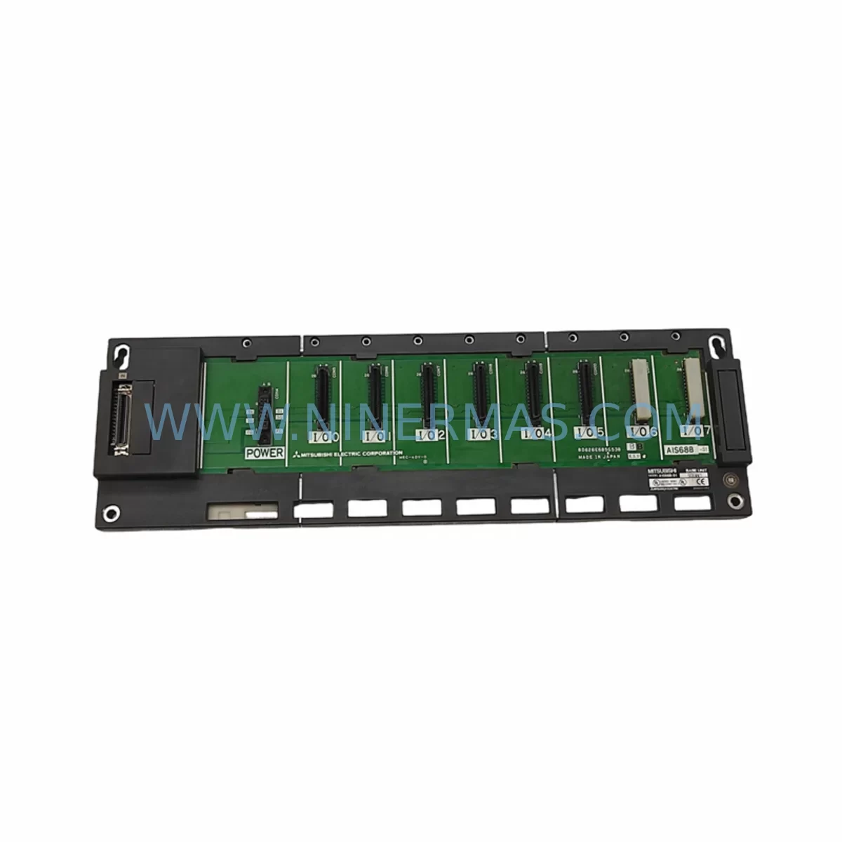
Mitsubishi A1S68B Retrofit-Compatible Expansion Base Module
Verify the part, confirm the platform family, and move straight into quotation with the right commercial details.
RFQ Ready
- SKUA1S68B
- CategoryPLC & Industrial Automation Modules
- BrandMitsubishi Electric
- SupportAvailability, lead time, condition, and shipping coordination
How Buyers Usually Use This Page
- Confirm the exact part number and platform family before sending the quote request.
- Use direct email when quantity, condition, and destination are already defined internally.
- Switch to the broader brand or category archive when you need alternates nearby.
Series Navigation
Move through the most common platform families behind this part.
Product RFQ
Send this part directly for quotation.
Include quantity, required condition, destination country, and target delivery timing. Current reference: Mitsubishi A1S68B Retrofit-Compatible Expansion Base Module with SKU A1S68B.
Mitsubishi A1S68B Retrofit-Compatible Expansion Base Module: Legacy System Compatibility & Smooth Upgrade Path
The Mitsubishi A1S68B is an 8-slot expansion base unit designed for the MELSEC-A series programmable logic controller platform. As Mitsubishi Electric has progressively phased out the MELSEC-A product line in favour of the MELSEC-Q and MELSEC-iQ-R series, the A1S68B has become a critical spare part for facilities operating legacy control panels, older discrete manufacturing lines, and process automation systems that were originally commissioned in the 1990s and early 2000s. NINERMAS maintains verified stock of the A1S68B to support planned and emergency retrofit projects, with pre-shipment functional testing and a 12-month warranty on every unit shipped.
For engineers managing ageing automation infrastructure, the A1S68B provides a direct, slot-compatible expansion path within existing MELSEC-A racks. It accepts standard A-series I/O modules, including digital input modules such as the A1SX40 and A1SX80, digital output modules such as the A1SY10 and A1SY80, and analogue I/O modules such as the A1S68AD and A1S62DA. This means that during a partial retrofit — where only the CPU or power supply is being upgraded — the existing I/O wiring, terminal block assignments, and field device connections can be preserved, dramatically reducing rewiring labour and the risk of wiring errors during recommissioning.
Upgrade Compatibility Table
| Parameter | A1S68B (This Unit) | Retrofit / Upgrade Notes |
|---|---|---|
| Slot Count | 8 slots | Compatible with all standard MELSEC-A series I/O and special function modules |
| Mounting | DIN rail / panel mount | Verify existing cabinet rail spacing; standard 35 mm DIN rail compatible |
| Power Supply Interface | A-series power supply connector (A1S61P / A1S62P compatible) | Confirm power supply capacity when adding high-current I/O modules |
| CPU Communication | MELSEC-A backplane bus | Not directly compatible with Q-series or iQ-R CPU without bus converter |
| Extension Cable | A1SC□B extension cable required for remote expansion | Maximum extension distance per Mitsubishi specification; verify cable length |
| Module Address Setting | Rotary switch on base unit | Must match GX Developer / GX Works2 I/O assignment; verify before power-on |
| Communication Protocol | MELSEC-A proprietary backplane bus | For Modbus or PROFIBUS migration, add A1SJ71UC24-R4 or A1SJ71PB92D |
| Replacement Recommendation | Direct drop-in for existing A1S68B installations | For new projects, consider MELSEC-Q QA1S6□B adapter base for Q-series migration |
| Commissioning Tool | GX Developer or GX Works2 | Backup existing program before any hardware swap; verify I/O map post-installation |
| Warranty | 12-Month Warranty — All units pre-shipment tested by NINERMAS technical team | |
Retrofit Planning for Existing Automation Systems
A successful retrofit using the A1S68B begins well before the unit arrives on site. The first step is a thorough audit of the existing control cabinet to document the current slot population, module types, and I/O addresses assigned in the PLC program. Engineers should record every module installed in the existing base — including any A1SJ71UC24-R4 serial communication modules used for RS-232C or RS-422 links to SCADA systems or HMI panels, and any A1SJ71E71-B5 Ethernet interface modules used for network connectivity. These communication modules must be reinstalled in the same logical slot positions in the replacement base, or the GX Developer program must be updated to reflect any slot changes before the system is restarted.
Power budget verification is a frequently overlooked step. The A1S61P or A1S62P power supply module feeding the base must have sufficient current capacity for all installed modules. When adding new I/O modules during the retrofit — for example, replacing a failed analogue module with a higher-channel-count A1S68AD — the total 5 VDC and 24 VDC current draw must be recalculated against the power supply’s rated output. Exceeding the power budget will cause intermittent faults or prevent the CPU from entering RUN mode.
Terminal block wiring is another critical checkpoint. The A1S68B itself does not carry field wiring — all field connections are made at the individual I/O module terminal blocks. However, when replacing a base unit, it is essential to photograph and document all wiring before removal. Modules such as the A1SX40 (16-point DC input) and A1SY10 (16-point relay output) use specific terminal block layouts, and any transposition of wires during reinstallation can cause incorrect field device operation or equipment damage. Using pre-wired terminal block connectors where available significantly reduces this risk.
For facilities that are simultaneously upgrading their HMI from an older Mitsubishi F940GOT or A985GOT graphic panel to a newer GT2107 or GT2715 GOT2000 series panel, the communication link between the HMI and the MELSEC-A CPU must be carefully managed. The GOT2000 series supports MELSEC-A CPU communication via the A-compatible driver, but the connection cable type and port settings must be verified in GT Designer3 before the new panel is powered on. Failure to configure the correct station number and baud rate will result in a communication timeout alarm on the HMI and loss of process visibility during the critical post-retrofit commissioning window.
Where the retrofit scope includes adding new I/O points — for example, to accommodate additional sensors or actuators added as part of a process improvement project — the A1S68B’s 8 slots provide sufficient capacity for most small-to-medium expansion requirements. Modules such as the A1SX80 (32-point DC input) or A1SY80 (32-point transistor output) can be added to unused slots, with new I/O addresses assigned in GX Developer and the ladder program updated accordingly. A full program backup to a memory cassette or PC before any hardware changes is mandatory.
Downtime Control During System Migration
Minimising production downtime during a MELSEC-A base unit replacement requires a structured pre-outage preparation process. Before the planned maintenance window, the engineering team should complete a full program backup using GX Developer, saving the project file to both a local PC and a removable memory cassette installed in the CPU. The I/O assignment table, comment data, and device memory should all be included in the backup. This ensures that if the CPU requires replacement alongside the base unit — a common scenario when the original CPU has accumulated significant operating hours — the program can be restored within minutes rather than hours.
During the outage, the recommended sequence is: power down the control panel in the correct order (field devices first, then I/O modules, then CPU, then power supply), remove all I/O modules from the old base unit in slot order while labelling each module with its slot number, install the replacement A1S68B, reinstall all modules in their original slot positions, reconnect the extension cable to the main base or CPU rack, restore power in reverse order, and verify the CPU enters RUN mode before releasing the system to operations. The entire process for an experienced technician typically takes 30 to 90 minutes depending on the number of modules and the complexity of the wiring.
For critical processes where even a 30-minute outage is unacceptable, a parallel commissioning approach can be used: the replacement base unit is pre-populated with spare modules and pre-wired on a temporary panel, the program is loaded and verified in offline simulation using GX Works2, and the cutover is performed as a rapid swap during a scheduled micro-outage. This approach is particularly effective in continuous process industries such as chemical, pharmaceutical, and food and beverage manufacturing, where the cost of an unplanned stoppage far exceeds the cost of the additional engineering preparation time.
NINERMAS supports downtime-critical projects by offering expedited order processing and same-day dispatch for in-stock units. All A1S68B units are tested prior to shipment to confirm backplane bus integrity and slot connector condition, reducing the risk of a DOA unit causing an extended outage. The 12-month warranty covers any latent defects identified after installation.
Retrofit Support FAQ
Q1: Is the A1S68B a direct replacement for my existing MELSEC-A expansion base?
Yes. The A1S68B is a standard 8-slot MELSEC-A series expansion base unit and is a direct mechanical and electrical replacement for other A1S68B units in existing installations. It accepts all standard MELSEC-A series I/O and special function modules without modification. If you are replacing a different slot-count base (such as the A1S65B 5-slot or A1S612B 12-slot), the slot count difference must be accounted for in your I/O assignment and program.
Q2: What commissioning steps are required after installing the replacement base?
After physical installation, verify that all module slot positions match the original configuration, confirm the base unit address switch setting matches the GX Developer I/O assignment, restore power in the correct sequence, and monitor the CPU diagnostic LEDs for any error codes. Use GX Developer or GX Works2 to perform an online connection test and verify that all I/O modules are recognised. Check communication module status if serial or Ethernet links are present. A full I/O force test is recommended before returning the system to automatic operation.
Q3: Can I use the A1S68B with a MELSEC-Q series CPU?
Not directly. The A1S68B uses the MELSEC-A proprietary backplane bus, which is not natively compatible with MELSEC-Q or MELSEC-iQ-R CPUs. Mitsubishi Electric produced the QA1S6□B series of A/Q mixed base units to support migration projects where A-series I/O modules needed to be retained alongside a Q-series CPU. If your project requires Q-series CPU performance with existing A-series I/O, the QA1S65B or QA1S68B adapter base is the recommended migration path.
Q4: What warranty and testing does NINERMAS provide with the A1S68B?
Every A1S68B unit supplied by NINERMAS is covered by a 12-month warranty from the date of shipment. Prior to dispatch, each unit undergoes a pre-shipment functional test to verify backplane bus continuity, slot connector integrity, and physical condition. Units are shipped with appropriate anti-static and protective packaging. In the event of a warranty claim, NINERMAS provides a replacement unit or repair service. For urgent retrofit projects, expedited shipping options are available — contact our technical sales team at sale@ninermas.com or +0086 187 5021 5667 to confirm stock availability and lead time.
| Product Series | MELSEC-A |
|---|---|
| Country of Origin | JP |
Catalog Continuation
More Mitsubishi Electric modules in the catalog.
Use the brand lane to compare nearby part numbers, platform-adjacent modules, and other inquiry-ready listings before sending your final RFQ.
SKU: A50CA55C BC186A433G53
Mitsubishi A50CA55C BC186A433G53 Spare Part for Maintenance
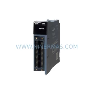
SKU: MELSEC RD77MS16 D 0140-76929 GAS N2, 40 SLM UFC-1660
Mitsubishi RD77MS16 Safety-Reliable Motion for Critical Sites
Catalog Continuation
Alternative parts within PLC & Industrial Automation Modules.
Stay inside the same system family when you need substitutes, adjacent modules, or a broader shortlist for procurement review.
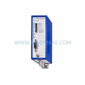
SKU: OZDPROFI12MG12
Hirschmann OZDPROFI12MG12 Spare Part for Industrial Maintenance
SKU: 07025-0000-70-1-04
KONTRON 07025-0000-70-1-04 Service-Ready Spare Part