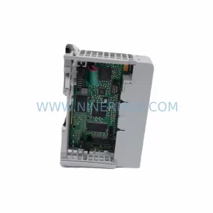
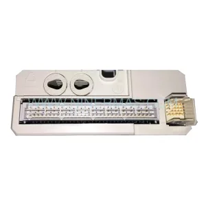
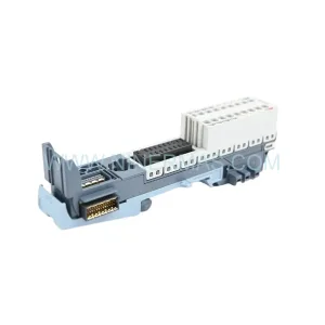
Original Industrial Spare Part
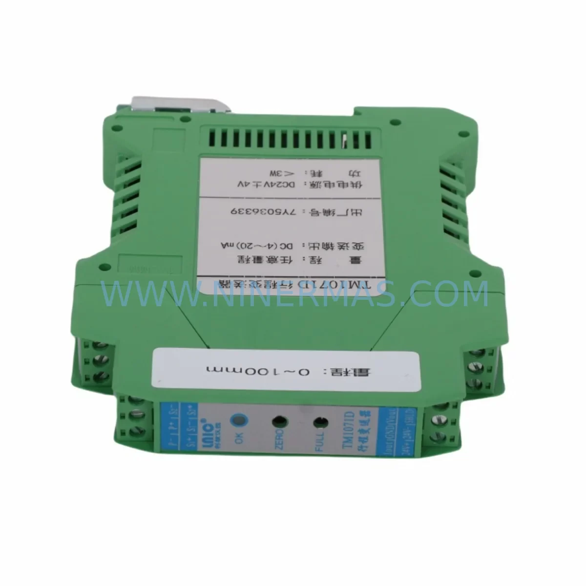
LNIC TM1071D Retrofit-Compatible Travel Transmitter
Verify the part, confirm the platform family, and move straight into quotation with the right commercial details.
RFQ Ready
- SKUTM1071D
- CategoryPLC & Industrial Automation Modules
- BrandLNIC
- SupportAvailability, lead time, condition, and shipping coordination
How Buyers Usually Use This Page
- Confirm the exact part number and platform family before sending the quote request.
- Use direct email when quantity, condition, and destination are already defined internally.
- Switch to the broader brand or category archive when you need alternates nearby.
Series Navigation
Move through the most common platform families behind this part.
Product RFQ
Send this part directly for quotation.
Include quantity, required condition, destination country, and target delivery timing. Current reference: LNIC TM1071D Retrofit-Compatible Travel Transmitter with SKU TM1071D.
LNIC TM1071D Retrofit-Compatible Travel Transmitter: Legacy System Compatibility & Smooth Upgrade
The LNIC TM1071D is a ruggedized travel transmitter engineered for demanding industrial environments and purpose-built to serve as a reliable retrofit solution for aging automation systems. As legacy control architectures reach end-of-life and OEM support for discontinued transmitter models is phased out, the TM1071D provides a technically sound, cost-effective replacement path that minimizes engineering rework and reduces unplanned downtime. Whether you are upgrading a legacy SCADA loop, restoring a decommissioned field instrument, or modernizing a distributed control system (DCS) panel, the TM1071D is designed to integrate with minimal disruption to existing wiring, signal conditioning, and control logic.
Industrial facilities operating older process control infrastructure frequently encounter the challenge of sourcing compatible spare parts for transmitters that have been discontinued by the original manufacturer. The TM1071D addresses this directly by maintaining electrical and mechanical compatibility with a broad range of legacy field devices. Its ruggedized housing is rated for harsh environments — including high-vibration, high-humidity, and wide-temperature-range installations — making it equally suitable for oil & gas, chemical processing, water treatment, and heavy manufacturing applications.
When planning a retrofit using the TM1071D, engineers should verify several critical parameters before installation. Power supply compatibility is the first checkpoint: confirm that the existing loop supply voltage (typically 24 VDC) and current capacity are sufficient to support the TM1071D’s operating range. Terminal wiring should be reviewed against the original transmitter’s terminal block layout; in most cases, the two-wire 4–20 mA loop connection is preserved, but polarity and shielding practices must be confirmed on-site. If the legacy system used a three-wire or four-wire transmitter, a signal conditioner or loop isolator may be required as an intermediate component.
For installations involving a PLC backplane or remote I/O rack, verify that the analog input module — such as an existing 4-channel or 8-channel AI card — is configured for the correct input range and resolution. Module address assignments in the PLC program must be cross-checked to ensure the TM1071D’s output maps correctly to the existing tag database. If the control system uses a HART-enabled analog input module, the TM1071D’s HART communication capability (where applicable) should be validated using a HART communicator or field device management tool before commissioning.
HMI screen updates are often overlooked during transmitter replacements. If the original transmitter had a unique engineering unit scaling or range, the corresponding HMI faceplate, trend display, and alarm setpoints must be updated to reflect the TM1071D’s calibrated output. This is particularly important in systems using SCADA software with hardcoded scaling parameters tied to the legacy device’s datasheet.
Communication protocol migration is another consideration for facilities transitioning from older 4–20 mA-only loops to hybrid HART or fieldbus architectures. The TM1071D supports standard analog signal transmission and is compatible with systems using Modbus RTU over RS-485 communication links where a signal converter is employed. For sites migrating toward PROFIBUS PA or Foundation Fieldbus, a protocol gateway or segment coupler will be required, and the TM1071D should be evaluated alongside the target fieldbus infrastructure.
Installation space confirmation is essential in retrofit projects where the control cabinet or field junction box has limited clearance. The TM1071D’s compact form factor is designed to fit standard DIN rail mounting configurations, and its terminal cover dimensions are compatible with most existing enclosure layouts. Where space is constrained, a slim-profile signal isolator or DIN rail power supply module can be co-mounted without requiring enclosure modification.
During the commissioning phase, field technicians should perform a full loop check from the TM1071D output terminals to the analog input card, verifying 4 mA at zero-percent process and 20 mA at full-scale. Span and zero adjustments should be made using the transmitter’s local configuration interface or a connected HART device. Where the legacy system used a handheld programming terminal or configuration cable, confirm compatibility with the TM1071D’s configuration port before on-site deployment.
For multi-loop upgrade projects, the TM1071D is frequently deployed alongside complementary components including LNIC signal isolators, loop-powered display modules, DIN rail terminal blocks, 24 VDC panel power supplies, and analog output modules for closed-loop control applications. In systems where the original transmitter interfaced with a legacy single-loop controller or PID station, the TM1071D’s output can be directly wired to the controller’s analog input without additional signal conditioning, provided the input impedance is within specification.
All TM1071D units supplied by NINERMAS are sourced from verified inventory channels, individually tested prior to shipment, and covered by a 12-month warranty. Stock availability is maintained to support urgent replacement requirements, and units can be dispatched with full test documentation upon request.
Upgrade Compatibility Table
| Parameter | Details |
|---|---|
| SKU | TM1071D |
| Brand / Series | LNIC / TM Series |
| Signal Output | 4–20 mA (2-wire loop-powered) |
| Supply Voltage | 24 VDC (nominal loop supply) |
| Mounting | DIN rail / panel mount compatible |
| Communication | Analog 4–20 mA; HART-compatible interface |
| Installation Space | Compact form factor; fits standard enclosures |
| Replacement Compatibility | Drop-in for legacy 2-wire travel transmitters; verify terminal layout |
| Commissioning Requirement | Loop check, span/zero calibration, HMI scaling update |
| Warranty | 12 months from date of shipment |
| Pre-shipment Testing | Yes — full loop test with documentation available |
| Stock Availability | In stock — ready for urgent dispatch |
Retrofit Planning for Existing Automation Systems
A successful retrofit begins well before the TM1071D arrives on-site. The engineering team should compile the original transmitter’s datasheet, loop drawing, and PLC I/O list to establish a baseline for comparison. In systems where the legacy transmitter was mounted on a multi-slot I/O backplane or connected through a marshalling cabinet terminal strip, the physical wiring path must be traced and labeled before removal.
For control systems using a remote I/O drop connected via PROFIBUS DP or DeviceNet, the TM1071D’s analog output will interface with the remote analog input module at the drop level. Confirm that the module’s channel configuration — input type, range, and filter settings — matches the TM1071D’s output characteristics. In older systems using legacy single-board controllers or rack-mounted PID modules, the transmitter’s 4–20 mA signal may feed directly into a dedicated analog input channel on the controller card.
Where the original installation included a loop-powered indicator or field-mounted display wired in series with the transmitter loop, verify that the combined loop burden — including the indicator, cable resistance, and input impedance of the AI module — remains within the TM1071D’s specified load capacity. If the burden exceeds the transmitter’s drive capability, a loop-powered signal splitter or active signal isolator should be inserted to buffer the output.
In projects involving control cabinet upgrades where the power distribution rail is being replaced alongside the transmitter, coordinate the sequencing of power-down and power-up events carefully. A 24 VDC DIN rail power supply with adequate current headroom should be selected to support all loop-powered devices on the same supply rail, including the TM1071D and any co-located signal conditioners or intrinsic safety barriers.
For facilities managing a phased upgrade across multiple process loops, the TM1071D can be introduced loop-by-loop without requiring a full system shutdown. This approach allows maintenance teams to validate each replacement individually, confirm PLC tag mapping, and update HMI graphics incrementally — significantly reducing the risk of widespread control disruption.
Downtime Control During System Migration
Minimizing downtime during a transmitter replacement requires a structured approach that protects the existing program logic, maintains field control continuity, and reduces the window of exposure to process upsets. Before removing the legacy transmitter, place the affected control loop in manual mode at the DCS or PLC operator station. This prevents the controller from responding to the loss of the 4–20 mA signal during the physical swap and avoids spurious alarms or automatic shutdowns triggered by an open-loop condition.
Where the process cannot tolerate even a brief interruption to measurement, a loop simulator or 4–20 mA signal source can be connected to the AI module input terminals to hold the last known process value while the TM1071D is installed and wired. Once the new transmitter is connected and powered, the simulated signal is removed and the loop is returned to automatic control after a brief stabilization period.
Preserving the original PLC program logic is non-negotiable. The TM1071D replacement should not require any ladder logic or function block modifications, provided the signal range and scaling are consistent with the legacy device. If the original transmitter used a non-standard range — for example, 1–5 V output or a custom HART variable mapping — the PLC’s analog input scaling block must be updated to reflect the TM1071D’s standard 4–20 mA output before returning the loop to automatic mode.
Post-installation, a structured commissioning checklist should be completed: verify loop current at 0% and 100% process, confirm alarm setpoints are active, validate HMI display values against a reference instrument, and document the as-left calibration data. This record supports future maintenance activities and provides evidence of compliance for facilities operating under ISO 9001 or IEC 61511 functional safety frameworks.
Retrofit Support FAQ
Q1: Is the LNIC TM1071D a direct drop-in replacement for my existing travel transmitter?
In most cases, yes. The TM1071D is designed to be compatible with standard 2-wire 4–20 mA loop installations. Before installation, compare the terminal block layout, housing dimensions, and process connection type against your existing transmitter. If the legacy unit used a non-standard wiring configuration or a proprietary connector, minor field adaptation may be required. Our technical team can assist with compatibility verification based on your original transmitter’s model number and datasheet.
Q2: What pre-shipment testing is performed on the TM1071D, and is documentation available?
All TM1071D units supplied by NINERMAS undergo a full loop test prior to shipment, verifying 4 mA output at zero-scale and 20 mA at full-scale under a calibrated load. Test documentation — including calibration records and inspection reports — is available upon request and can be provided with the shipment for traceability purposes.
Q3: Can the TM1071D be used in a HART-enabled control system?
The TM1071D supports standard 4–20 mA analog output and is compatible with HART-enabled analog input modules where the HART signal is superimposed on the loop current. Confirm with your AI module’s specification that it supports HART pass-through or multidrop configuration if HART communication is required for asset management or remote configuration purposes.
Q4: What warranty and after-sales support is provided?
All TM1071D units are covered by a 12-month warranty from the date of shipment. NINERMAS maintains in-stock inventory to support urgent replacement requirements, and our technical team is available to assist with wiring, commissioning, and compatibility questions. Contact us at sale@ninermas.com or +0086 187 5021 5667 for support.
| Product Series | Other series |
|---|
Catalog Continuation
Alternative parts within PLC & Industrial Automation Modules.
Stay inside the same system family when you need substitutes, adjacent modules, or a broader shortlist for procurement review.
SKU: 16-167627-00 8122 410 05002, 4022.470.78191 8122 410 55702 16-273491-00
Novellus 16-167627-00 Service-Ready Industrial Spare Part
SKU: 2305451-C DT2000 0626 P2, OLE36-10632-02
Advanced Energy 2305451-C Service-Ready Industrial Spare Part