Original Industrial Spare Part
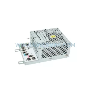
KUKA 00-228-934 Retrofit-Compatible EMD for Legacy KRC2 Systems
Verify the part, confirm the platform family, and move straight into quotation with the right commercial details.
RFQ Ready
- SKUKRC2 00-228-934 KRC4EMD 00-228-936 00-168-334
- CategoryPLC & Industrial Automation Modules
- BrandKUKA
- SupportAvailability, lead time, condition, and shipping coordination
How Buyers Usually Use This Page
- Confirm the exact part number and platform family before sending the quote request.
- Use direct email when quantity, condition, and destination are already defined internally.
- Switch to the broader brand or category archive when you need alternates nearby.
Series Navigation
Move through the most common platform families behind this part.
Product RFQ
Send this part directly for quotation.
Include quantity, required condition, destination country, and target delivery timing. Current reference: KUKA 00-228-934 Retrofit-Compatible EMD for Legacy KRC2 Systems with SKU KRC2 00-228-934 KRC4EMD 00-228-936 00-168-334.
KUKA 00-228-934 Retrofit-Compatible EMD for Legacy KRC2 Systems
The KUKA 00-228-934 Energy Management Device (EMD) is a critical power regulation and energy recovery module originally designed for the KRC2 robot controller platform. As KUKA progressively transitions its installed base toward the KRC4 and KRC4 compact architectures, many production facilities operating legacy KRC2 cells face the challenge of sourcing compatible spare parts, managing end-of-life component risk, and executing controlled system upgrades without disrupting ongoing production schedules. This listing covers three interrelated part numbers — 00-228-934, 00-228-936, and 00-168-334 — which represent the primary EMD variants used across KRC2 and KRC4 EMD series controllers in automotive, general manufacturing, and heavy-industry robotic applications.
The EMD module manages regenerative braking energy from the servo axes, converting kinetic energy back into usable DC bus power and protecting the drive system from overvoltage conditions during deceleration. In legacy KRC2 installations, the 00-228-934 works in conjunction with the KPP 600-20 (KUKA Power Pack) and KSP 600-3×64 servo drives to maintain stable DC bus voltage across all six robot axes. Failure of the EMD typically manifests as E-Stop faults, DC bus overvoltage alarms, or erratic axis behavior during high-inertia deceleration cycles — all of which result in unplanned downtime and potential damage to downstream drive components.
For facilities planning a controlled migration from KRC2 to KRC4 EMD architecture, the 00-228-936 and 00-168-334 variants provide the updated interface and firmware compatibility required by the KRC4 EMD controller backplane. Engineers should verify the existing cabinet wiring harness, particularly the X11 power cable routing and the DC bus bar connections, before substituting modules between KRC2 and KRC4 EMD frames. The KPS 600-20 power supply module and the CCU (Cabinet Control Unit) board must also be confirmed as compatible with the target EMD variant to avoid communication faults on the KUKA System Bus (KSB).
Upgrade Compatibility Table
| Parameter | KRC2 (00-228-934) | KRC4 EMD (00-228-936 / 00-168-334) |
|---|---|---|
| DC Bus Voltage | 600 V DC nominal | 600 V DC nominal |
| Backplane Interface | KRC2 VME-style backplane | KRC4 EMD proprietary backplane |
| Communication Protocol | KUKA System Bus (KSB) / CAN | EtherCAT / KSB |
| Mounting Dimensions | Standard KRC2 cabinet slot | KRC4 EMD cabinet slot (verify depth) |
| Replacement Path | Direct swap within KRC2 fleet | Requires KRC4 EMD cabinet and CCU |
| Commissioning Tool | WorkVisual 3.x / KCP2 pendant | WorkVisual 5.x / KCP4 pendant |
| Firmware Compatibility | KSS 5.x | KSS 8.x |
| Pre-Shipment Testing | Yes — functional load test | Yes — functional load test |
| Warranty | 12 Months | 12 Months |
Retrofit Planning for Existing Automation Systems
A successful KRC2 EMD replacement or KRC4 EMD upgrade begins with a thorough audit of the existing control cabinet. Before removing the 00-228-934, engineers should document the current DC bus voltage readings, record all active fault codes from the KCP2 teach pendant, and photograph the existing wiring layout at the X11 and X21 terminal blocks. The RDC (Resolver-to-Digital Converter) module mounted on the robot arm must also be checked for firmware version compatibility, as mismatched RDC firmware can generate axis calibration errors after an EMD swap even when the mechanical installation is correct.
When upgrading to the KRC4 EMD platform using the 00-228-936 or 00-168-334, the project scope typically expands to include replacement of the CCU board, the SIB (Safety Interface Board), and the DSE-IBS (Drive System Electronics – InterBus) interface card. Each of these components must be ordered and staged before the maintenance window begins to avoid extended downtime. The KPS 600-20 power supply should be tested under load prior to the upgrade, as aging capacitors in legacy KPS units can cause instability in the new EMD’s energy recovery circuit.
I/O mapping is another critical step. Legacy KRC2 systems often use hardwired I/O through the X11 cabinet interface, while KRC4 EMD systems may route digital I/O through EtherCAT-based I/O modules. If the facility’s PLC or safety relay logic depends on specific terminal assignments at the X11 block, those assignments must be remapped in WorkVisual before the new controller goes live. HMI screens linked to robot status signals — such as program running, fault active, and speed override — must also be updated to reflect any changes in signal naming or address offset introduced by the KSS 8.x operating system.
For multi-robot cells, it is advisable to complete the EMD retrofit on one robot at a time, keeping adjacent robots in a known-good state so that cell-level production can continue at reduced capacity during the maintenance window. The KCP4 teach pendant should be used to verify axis mastering data after each EMD replacement, and a full program dry-run at reduced speed (10–25%) should be completed before returning the robot to automatic mode.
Downtime Control During System Migration
Minimizing unplanned downtime during an EMD replacement requires pre-staging all replacement components, including the 00-228-934 or 00-228-936 module, the X11 power cable, and any associated CCU or SIB boards, at the work site before the maintenance window opens. A recommended sequence is: (1) archive the current robot program and mastering data using WorkVisual or a USB backup from the KCP2/KCP4 pendant; (2) de-energize the cabinet and verify zero-energy state at the DC bus using a calibrated voltmeter; (3) remove the failed EMD and install the replacement, ensuring all backplane connectors are fully seated; (4) restore power and verify DC bus voltage stabilization before enabling drives; (5) reload the archived program and confirm axis mastering; (6) perform a supervised test cycle at reduced speed before releasing to production.
Original program logic is preserved throughout this process because the KRC2 and KRC4 EMD platforms store program files on the controller’s internal CompactFlash or SSD media, not on the EMD module itself. The EMD replacement does not erase or alter stored programs, provided the controller power-down sequence is followed correctly. Safety circuit continuity — including the SIB board’s emergency stop chain and the external safety relay inputs at the X11 block — must be verified with a functional safety test before the robot is returned to automatic operation. This step is non-negotiable in safety-critical environments such as automotive body shops, press lines, and palletizing cells.
All units supplied by NINERMAS are pre-tested under simulated load conditions prior to shipment, with test records available upon request. Reserved inventory programs are available for high-volume customers requiring guaranteed lead times and long-term spare parts supply commitments beyond standard stock levels.
Retrofit Support FAQ
Q1: Can the KUKA 00-228-934 be used as a direct replacement for the 00-228-936 without additional hardware changes?
A: Not directly. The 00-228-934 is designed for the KRC2 backplane, while the 00-228-936 targets the KRC4 EMD backplane. Cross-platform substitution requires cabinet-level changes including a new CCU board and updated wiring harness. Within the same platform (KRC2-to-KRC2 or KRC4 EMD-to-KRC4 EMD), direct swap is supported.
Q2: What commissioning steps are required after installing a replacement EMD?
A: After installation, restore DC bus power and confirm voltage stabilization. Use WorkVisual to verify drive configuration and check for communication faults on the KSB or EtherCAT network. Confirm axis mastering data via the KCP2 or KCP4 teach pendant, then perform a supervised test cycle at 10–25% speed before returning to automatic mode.
Q3: Does NINERMAS provide pre-shipment testing for the 00-228-934 and related EMD modules?
A: Yes. All EMD modules are functionally tested under simulated load conditions before shipment. Test records are available upon request. Each unit is covered by a 12-month warranty from the date of delivery, covering manufacturing defects and functional failures under normal operating conditions.
Q4: What is the typical lead time and inventory availability for the 00-228-934, 00-228-936, and 00-168-334?
A: NINERMAS maintains reserved stock for all three part numbers to support urgent replacement requirements. Standard lead time is 3–7 business days for in-stock units. Long-term supply agreements and reserved inventory programs are available for customers with ongoing maintenance contracts or multi-robot fleet requirements. Contact sale@ninermas.com for current stock levels and pricing.
| Product Series | Legacy KRC2 |
|---|---|
| Country of Origin | DE |
Catalog Continuation
More KUKA modules in the catalog.
Use the brand lane to compare nearby part numbers, platform-adjacent modules, and other inquiry-ready listings before sending your final RFQ.
SKU: 033.56.84.10C 033.56.84.10D
KUKA 033.56.84.10C/10D Retrofit-Compatible Gearbox for Legacy Systems
Catalog Continuation
Alternative parts within PLC & Industrial Automation Modules.
Stay inside the same system family when you need substitutes, adjacent modules, or a broader shortlist for procurement review.
SKU: BFK458-25 (400 N.M) 180VDC
Lenze BFK458-25 400NM 180VDC Service-Ready Spare Part
SKU: 6ES7138-4CF03-0AB0
Siemens 6ES7138-4CF03-0AB0 Service-Ready Spare Part for Industrial Maintenance