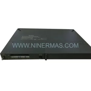
Original Industrial Spare Part
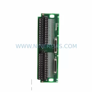
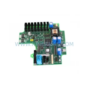
VME1-2 04-719030-01 Retrofit-Compatible VME Bus Extender
Verify the part, confirm the platform family, and move straight into quotation with the right commercial details.
RFQ Ready
- SKUVME1-2 04-719030-01
- CategoryPLC & Industrial Automation Modules
- BrandIndustrial Control Hub
- SupportAvailability, lead time, condition, and shipping coordination
How Buyers Usually Use This Page
- Confirm the exact part number and platform family before sending the quote request.
- Use direct email when quantity, condition, and destination are already defined internally.
- Switch to the broader brand or category archive when you need alternates nearby.
Series Navigation
Move through the most common platform families behind this part.
Product RFQ
Send this part directly for quotation.
Include quantity, required condition, destination country, and target delivery timing. Current reference: VME1-2 04-719030-01 Retrofit-Compatible VME Bus Extender with SKU VME1-2 04-719030-01.
NINERMAS VME1-2 04-719030-01 Retrofit-Compatible VME Bus Extender for Legacy Automation Systems
The NINERMAS VME1-2 04-719030-01 is a ruggedized VME bus extender module engineered for seamless integration into existing VME-based automation architectures. Designed with legacy system compatibility at its core, this module enables engineers and maintenance teams to extend, modernize, and stabilize aging control infrastructure without requiring a full platform migration. Whether you are managing a brownfield retrofit, replacing a discontinued spare part, or upgrading a control cabinet that has been in continuous service for over a decade, the VME1-2 04-719030-01 delivers the electrical and mechanical compatibility needed to restore system integrity and extend operational life.
In industrial environments where VMEbus backplanes remain the backbone of mission-critical control systems — including process automation, power generation, rail signaling, and defense electronics — sourcing a reliable replacement for an end-of-life extender module is often the difference between a planned maintenance window and an unscheduled production shutdown. The VME1-2 04-719030-01 addresses this challenge directly, offering a verified drop-in replacement path for legacy extender configurations while supporting the physical and electrical demands of harsh operating environments.
Upgrade Compatibility Table
| Parameter | VME1-2 04-719030-01 Specification | Retrofit Notes |
|---|---|---|
| Bus Standard | VMEbus (IEEE 1014) | Compatible with VME64, VME64x backplanes with adapter verification |
| Form Factor | Ruggedized VME module | Confirm slot pitch and card guide dimensions before installation |
| Power Input | +5 VDC, ±12 VDC (VME standard rails) | Verify PSU capacity; legacy power supplies may require derating assessment |
| Connector Interface | P1/P2 VME backplane connectors | Inspect backplane connector condition; replace worn P2 connectors if necessary |
| Communication Compatibility | Parallel VMEbus data/address lines | No protocol conversion required for standard VME masters |
| Installation Space | Standard VME card slot | Measure available rack unit space; confirm no mechanical interference with adjacent modules |
| Replacement Recommendation | Direct replacement for VME1-2 series extenders | Cross-reference OEM part number 04-719030-01 before ordering |
| Commissioning Focus | Bus termination, slot addressing, signal integrity | Use VME bus analyzer to verify signal quality post-installation |
| Warranty | 12-Month Warranty | Covers manufacturing defects; includes pre-shipment functional test report |
Retrofit Planning for Existing Automation Systems
Successful integration of the VME1-2 04-719030-01 into a legacy control system begins well before the module arrives on site. Retrofit planning must account for the full scope of the existing architecture, including the VME backplane configuration, the power supply module feeding the rack, and the controller cards occupying adjacent slots. In many installations, the VME chassis houses a combination of CPU boards, I/O modules, and communication cards that have been in service for years without modification. Introducing a new extender module into this environment requires careful attention to slot addressing and bus arbitration settings to avoid conflicts with existing VME masters.
When the control system includes a programmable logic controller interfacing with the VME rack — such as a legacy MVME processor board or a third-party VME SBC — the retrofit team must verify that the extender does not alter the bus cycle timing or introduce signal reflections that could affect data integrity. In systems where the VME rack communicates upstream to a SCADA platform or DCS via a serial or Ethernet gateway module, the communication link must be validated after the extender is installed to confirm that no address mapping or polling configuration has been disrupted.
For control cabinets that also house an HMI panel connected to the VME controller via a serial RS-232 or RS-485 link, the HMI screen mapping should be reviewed after the retrofit to ensure that all process variable displays and alarm setpoints remain correctly associated with the underlying I/O channels. In cases where the legacy system uses a VME-based analog input module or digital output module for field device interfacing, the wiring termination at the I/O module’s terminal block must be documented and verified against the original as-built drawings before the system is returned to service.
Power budget analysis is a critical step that is frequently overlooked during VME retrofit projects. The existing power supply module in the rack must be assessed for available headroom on the +5 VDC and ±12 VDC rails. If the current PSU is operating near its rated capacity, adding the VME1-2 04-719030-01 may require either upgrading to a higher-capacity power supply or redistributing loads across multiple supply units. In multi-chassis configurations where a VME bus extender bridges two separate racks, the cable length and signal integrity between the local and remote chassis must be evaluated using appropriate test equipment before the system is commissioned.
Signal isolation requirements should also be reviewed during the planning phase. In environments with significant electrical noise — such as those adjacent to variable frequency drives, large motor starters, or high-current switching equipment — the addition of a signal isolator or optocoupler module between the VME rack and field wiring may be necessary to protect the extender and associated I/O cards from transient damage. Programming cable access for the VME CPU board should be confirmed as part of the pre-retrofit checklist, as some chassis configurations restrict physical access to the programming port once all slots are populated.
Downtime Control During System Migration
Minimizing unplanned downtime during a VME extender replacement is a primary concern for any maintenance team responsible for continuous process operations. The most effective approach is to complete as much preparation work as possible while the system remains online. This includes photographing all existing wiring connections, downloading a backup of the current PLC program from the VME CPU board, and documenting the current slot configuration and module addresses before any hardware is disturbed.
Where the process permits a controlled shutdown, the replacement sequence should be planned to keep the total time with the VME bus de-energized as short as possible. The VME1-2 04-719030-01 should be pre-configured and bench-tested before it is brought to the installation site. If the system includes a redundant control path — for example, a secondary VME rack or a hot-standby controller — the switchover to the backup path should be executed and verified before the primary rack is taken offline.
After the new extender module is installed and the rack is re-energized, the commissioning sequence should follow a structured approach: verify bus power levels, confirm module recognition by the VME master, check I/O channel status against the pre-shutdown baseline, and validate communication link integrity to all connected devices. The original PLC program logic should be confirmed as intact by comparing the uploaded program against the pre-shutdown backup. HMI displays should be cycled through all screens to verify that process variable readings are consistent with field instrument signals. Any discrepancies in analog scaling, digital input state, or communication timeout parameters should be resolved before the system is returned to automatic control mode.
Pre-shipment functional testing of the VME1-2 04-719030-01 is performed prior to dispatch, and a test report is available upon request. This testing reduces the risk of receiving a non-functional module and supports the goal of completing the retrofit within a single planned maintenance window. All units are covered by a 12-month warranty against manufacturing defects, providing assurance for both the immediate installation and the ongoing operational period.
Retrofit Support FAQ
Q: Is the VME1-2 04-719030-01 a direct replacement for the original OEM part?
A: The VME1-2 04-719030-01 is designed as a retrofit-compatible replacement for legacy VME bus extender modules of the same series. Customers should cross-reference the OEM part number 04-719030-01 and confirm the physical and electrical specifications against their existing installation before ordering. Our technical team can assist with compatibility verification based on your system documentation.
Q: What commissioning steps are required after installation?
A: After installing the module, verify VME bus power levels on all rails, confirm that the VME master recognizes the extender in the expected slot, validate I/O channel status, and check all communication links to connected devices including HMI panels and upstream SCADA or DCS systems. A full functional test of the PLC program logic should be performed before returning the system to automatic operation.
Q: Can this module be used in systems with mixed VME and VME64 modules?
A: The VME1-2 04-719030-01 is based on the standard VMEbus (IEEE 1014) specification. Use in mixed VME and VME64 environments is possible in many configurations, but customers should verify backplane connector compatibility and bus arbitration settings with their system integrator or our technical support team prior to installation.
Q: What does the 12-month warranty cover, and is pre-shipment testing included?
A: The 12-month warranty covers manufacturing defects identified during normal operation. Each unit undergoes pre-shipment functional testing before dispatch, and a test report is available upon request. Warranty claims are processed through our standard RMA procedure. For warranty inquiries or technical support, contact our team directly.
| Product Series | Other series |
|---|
Catalog Continuation
More Industrial Control Hub modules in the catalog.
Use the brand lane to compare nearby part numbers, platform-adjacent modules, and other inquiry-ready listings before sending your final RFQ.
Catalog Continuation
Alternative parts within PLC & Industrial Automation Modules.
Stay inside the same system family when you need substitutes, adjacent modules, or a broader shortlist for procurement review.
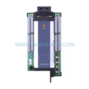
SKU: KRC4 00-168-334 00-181-563 KRC2 00-126-383 KRC2RDW 00-119-966
KUKA 00-168-334 Retrofit-Compatible Controller for Legacy Systems