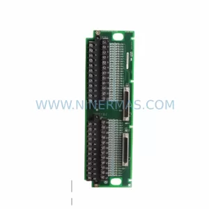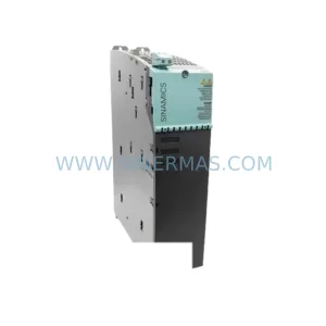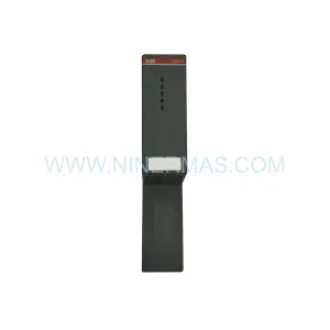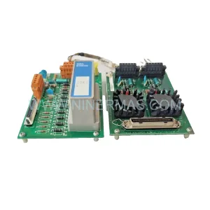
Original Industrial Spare Part
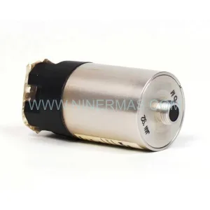
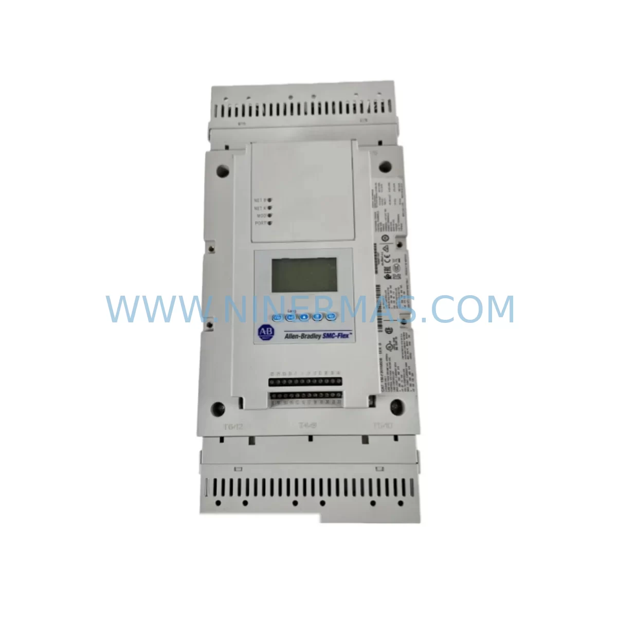
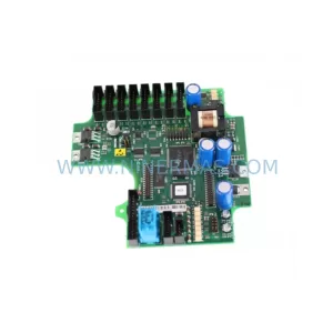
150-F201NBDB Retrofit-Compatible Motor Controller
Verify the part, confirm the platform family, and move straight into quotation with the right commercial details.
RFQ Ready
- SKU150-F201NBDB
- CategoryPLC & Industrial Automation Modules
- BrandIndustrial Control Hub
- SupportAvailability, lead time, condition, and shipping coordination
How Buyers Usually Use This Page
- Confirm the exact part number and platform family before sending the quote request.
- Use direct email when quantity, condition, and destination are already defined internally.
- Switch to the broader brand or category archive when you need alternates nearby.
Series Navigation
Move through the most common platform families behind this part.
Product RFQ
Send this part directly for quotation.
Include quantity, required condition, destination country, and target delivery timing. Current reference: 150-F201NBDB Retrofit-Compatible Motor Controller with SKU 150-F201NBDB.
NINERMAS 150-F201NBDB Retrofit-Compatible Motor Controller: Legacy System Compatibility & Smooth Upgrade
The NINERMAS 150-F201NBDB is a ruggedized, retrofit-compatible smart motor controller engineered for seamless integration into aging automation infrastructures. Whether you are replacing a discontinued drive module, modernizing a legacy control cabinet, or extending the service life of an existing production line, the 150-F201NBDB delivers the electrical compatibility, communication flexibility, and physical form factor required for a low-risk, minimal-downtime migration.
Designed with the realities of brownfield automation in mind, this unit supports direct substitution for a wide range of obsolete motor control modules commonly found in legacy PLC-based systems. Engineers and maintenance teams working on retrofit projects will find that the 150-F201NBDB reduces the complexity of panel rewiring, minimizes the need for custom adapter brackets, and supports the communication protocols already present in the existing control architecture.
Upgrade Compatibility Table
| Parameter | Details |
|---|---|
| Replaces / Compatible With | Legacy smart motor controller modules in equivalent form factor and power class |
| Mounting & Installation | Standard DIN rail and panel mount; fits existing cutouts in most legacy control cabinets |
| Communication Compatibility | Supports RS-485 Modbus RTU; adaptable to DeviceNet and Profibus via gateway modules |
| I/O Interface | Compatible terminal block pitch; direct wire-for-wire substitution on most legacy wiring harnesses |
| Power Supply Range | Wide-range input accommodates legacy 24 VDC and 120/240 VAC control power configurations |
| Retrofit Recommendation | Verify backplane slot assignment and module address before commissioning; update HMI tag references |
| Commissioning Notes | Confirm motor nameplate data, overload settings, and communication node address prior to first run |
| Warranty | 12-Month Warranty — covers manufacturing defects and functional failure under normal operating conditions |
Retrofit Planning for Existing Automation Systems
Successful integration of the 150-F201NBDB into an existing system begins well before the unit arrives on site. Retrofit planning should start with a thorough audit of the existing control cabinet, including a review of the power distribution architecture, terminal block layout, and available backplane slots. In many legacy installations, the control power bus is shared across multiple modules — including 24 VDC I/O expansion modules, analog input cards, and communication interface units — so confirming that the existing power supply module has sufficient residual capacity to support the 150-F201NBDB is a critical first step.
Terminal wiring compatibility is another key consideration. The 150-F201NBDB uses a standard screw-terminal interface that aligns with the pitch and labeling conventions of most legacy motor control wiring. However, engineers should cross-reference the existing wiring diagram against the 150-F201NBDB terminal assignment table to confirm that control signal wiring — including start/stop commands, fault relay outputs, and speed reference inputs — maps correctly without requiring intermediate signal conditioning or relay interposing.
For systems that rely on a rack-mounted backplane architecture, the physical slot position and module address assignment must be verified before installation. In many legacy PLC platforms, the rack chassis and backplane bus determine how the controller communicates with the CPU module. If the 150-F201NBDB is replacing a module at a specific rack address, the address switches or DIP settings on the new unit must be configured to match the original assignment to avoid communication faults at startup.
Communication protocol migration is a common challenge in retrofit projects. Many older systems use RS-485 Modbus RTU as the primary fieldbus, while newer control platforms may require PROFIBUS DP or EtherNet/IP. The 150-F201NBDB natively supports Modbus RTU, making it immediately compatible with existing HMI panels and SCADA systems that poll motor status, run-hours, and fault codes over the serial bus. For sites migrating to Ethernet-based protocols, a protocol gateway or communication bridge module can be inserted between the 150-F201NBDB and the new network infrastructure without requiring changes to the motor controller’s internal configuration.
HMI screen updates are often overlooked during motor controller replacements. If the existing operator panel references specific register addresses or device tags tied to the old module, those references must be updated to reflect the 150-F201NBDB’s register map. This is particularly important for fault code displays, motor current readouts, and remote start/stop status indicators. Coordinating HMI updates with the physical installation reduces the risk of operator confusion during the first post-retrofit production run.
I/O expansion requirements should also be assessed during the planning phase. In systems where the legacy motor controller was connected to a discrete I/O module for auxiliary contact monitoring or interlocking, the 150-F201NBDB’s onboard I/O capacity should be compared against the existing I/O module’s point count. If additional I/O is required, a supplementary I/O expansion module can be added to the rack without disrupting the primary control logic.
Signal isolation is another area that deserves attention, particularly in environments with high electrical noise from variable frequency drives, welding equipment, or large motor starters. Installing a signal isolator or barrier module between the 150-F201NBDB’s analog reference input and the upstream controller output can prevent noise-induced faults and improve long-term reliability. Similarly, shielded cable and proper grounding of the cable shield at a single point are recommended for all analog and communication wiring runs.
Programming cable compatibility should be confirmed before the commissioning team arrives on site. Many legacy motor controllers use proprietary programming interfaces that are not compatible with standard USB-to-serial adapters. The 150-F201NBDB supports standard RS-232 and USB programming interfaces, which simplifies parameter upload and download during commissioning and eliminates the need for specialized legacy programming tools.
Downtime Control During System Migration
Minimizing production downtime during a motor controller replacement requires a structured migration plan that addresses pre-staging, parallel testing, and rapid cutover procedures. The most effective approach is to pre-configure the 150-F201NBDB on the bench before the scheduled maintenance window, loading all motor parameters, communication settings, and protection thresholds in advance so that the on-site installation is limited to physical mounting, terminal connection, and a brief functional verification.
Preserving the original control program logic is essential. Before removing the legacy motor controller, the existing PLC program should be backed up to a programming terminal and stored in a secure location. If the legacy controller contains onboard parameter storage — such as motor nameplate data, overload trip curves, or PID tuning values — those parameters should be documented and transferred to the 150-F201NBDB configuration before the cutover. This ensures that the replacement unit behaves identically to the original from the perspective of the upstream PLC and the downstream motor.
For critical production lines where even a brief interruption is unacceptable, a staged migration approach can be used. In this approach, the 150-F201NBDB is installed in a parallel test circuit alongside the existing motor controller, allowing the new unit to be verified under load conditions before the final cutover. Once the test results confirm correct operation, the cutover can be completed during a planned maintenance window with confidence that the replacement unit will perform as expected.
Field commissioning should include a full functional test of all control modes — local, remote, and automatic — as well as verification of all protection functions, including overload, phase loss, and communication fault responses. The 150-F201NBDB’s built-in diagnostic LEDs and fault log simplify this process by providing immediate visual feedback on communication status, power supply health, and motor protection state. A successful commissioning sign-off should confirm that all HMI displays are reading correctly, all interlocks are functioning as designed, and the motor is running within its nameplate parameters.
Retrofit Support FAQ
Q: Is the 150-F201NBDB a direct drop-in replacement for my existing motor controller?
A: In most cases, yes. The 150-F201NBDB is designed to match the electrical interface, terminal layout, and communication protocol of a wide range of legacy smart motor controllers. However, we recommend verifying the power supply voltage, terminal pitch, and communication protocol against your existing wiring diagram before ordering to confirm compatibility.
Q: What commissioning steps are required after installation?
A: After physical installation and terminal connection, you will need to configure the motor nameplate parameters (rated current, voltage, and frequency), set the communication node address to match the original module, and verify that the HMI and PLC are reading the correct register values. A full functional test — including local start/stop, remote command, and fault simulation — should be completed before returning the system to production.
Q: Does the 150-F201NBDB ship pre-tested?
A: Yes. Every unit undergoes a factory functional test prior to shipment, including power-on verification, communication interface check, and protection function validation. A test report is available upon request. Units are shipped with all factory default parameters loaded and ready for site-specific configuration.
Q: What does the 12-month warranty cover?
A: The 12-month warranty covers manufacturing defects and functional failures under normal operating conditions from the date of shipment. It includes free repair or replacement of defective units. The warranty does not cover damage resulting from incorrect installation, overvoltage, physical impact, or unauthorized modification. Our technical support team is available to assist with installation questions and commissioning guidance throughout the warranty period.
| Product Series | Other series |
|---|
Catalog Continuation
More Industrial Control Hub modules in the catalog.
Use the brand lane to compare nearby part numbers, platform-adjacent modules, and other inquiry-ready listings before sending your final RFQ.
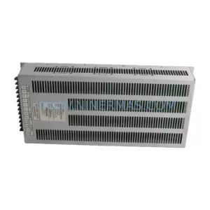
SKU: 80026-088-01 80026-088-01-R HBC65-Q7594
80026-088-01 Safety-Reliable Power Supply Module
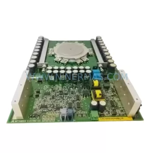
SKU: VME1-2 04-719030-01
VME1-2 04-719030-01 Retrofit-Compatible VME Bus Extender
Catalog Continuation
Alternative parts within PLC & Industrial Automation Modules.
Stay inside the same system family when you need substitutes, adjacent modules, or a broader shortlist for procurement review.
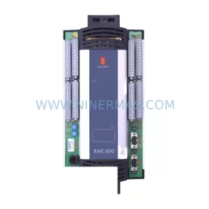
SKU: KRC4 00-168-334 00-181-563 KRC2 00-126-383 KRC2RDW 00-119-966
KUKA 00-168-334 Retrofit-Compatible Controller for Legacy Systems