Original Industrial Spare Part
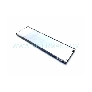
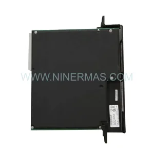
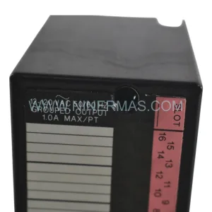
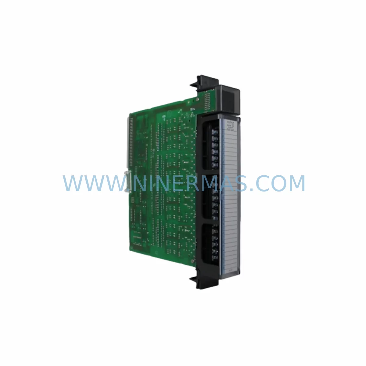
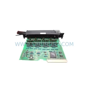
GE IC697MDL241 Retrofit-Compatible Discrete Input Module
Verify the part, confirm the platform family, and move straight into quotation with the right commercial details.
RFQ Ready
- SKUIC697MDL241
- CategoryPLC & Industrial Automation Modules
- BrandGE
- SupportAvailability, lead time, condition, and shipping coordination
How Buyers Usually Use This Page
- Confirm the exact part number and platform family before sending the quote request.
- Use direct email when quantity, condition, and destination are already defined internally.
- Switch to the broader brand or category archive when you need alternates nearby.
Series Navigation
Move through the most common platform families behind this part.
Product RFQ
Send this part directly for quotation.
Include quantity, required condition, destination country, and target delivery timing. Current reference: GE IC697MDL241 Retrofit-Compatible Discrete Input Module with SKU IC697MDL241.
GE IC697MDL241 Retrofit-Compatible Discrete Input Module: Legacy System Compatibility & Smooth Upgrade
The GE IC697MDL241 is a 32-point, 24VDC discrete input module designed for the GE Series 90-70 PLC rack architecture. As production lines age and original GE Fanuc components approach or exceed their published end-of-life dates, the IC697MDL241 remains one of the most sought-after retrofit solutions for engineers tasked with sustaining legacy automation infrastructure without committing to a full platform migration. NINERMAS maintains verified in-stock inventory of the IC697MDL241, fully tested and backed by a 12-month warranty, to support planned maintenance windows, emergency breakdowns, and long-term spare-parts programs.
Upgrade Compatibility Table
| Parameter | IC697MDL241 Specification | Retrofit / Upgrade Notes |
|---|---|---|
| Input Points | 32 points, 24VDC | Verify field wiring terminal block pitch matches existing IC697MDL240 or IC697MDL241A installations |
| Rack Compatibility | IC697CHS750 / IC697CHS782 / IC697CHS790 Series 90-70 racks | Confirm available slot count; module occupies one single-width slot |
| Backplane Interface | Series 90-70 VME-based backplane | Not compatible with Series 90-30 (IC693) or PACSystems RX7i backplanes without rack replacement |
| Communication Protocol | Backplane I/O bus (no standalone Ethernet/Profibus port) | If migrating to Profibus DP, pair with IC697BEM731 bus expansion module |
| Power Consumption | Confirm with IC697PWR710 / IC697PWR711 power supply capacity | Recalculate total rack load when adding modules during expansion |
| Module Addressing | Configured via Logicmaster 90 or Proficy Machine Edition | Preserve %I reference address assignments from original program before hot-swap |
| Installation Space | Single VME slot, standard Series 90-70 form factor | No mechanical modification required for direct slot replacement |
| Replacement Recommendation | Direct drop-in for IC697MDL241, IC697MDL240 | Verify firmware revision compatibility with CPU IC697CPU772 / IC697CPU781 |
| Commissioning Focus | %I address map, input filter timing, diagnostic enable bits | Use Proficy ME I/O configuration tool to validate point-by-point after installation |
| Warranty | 12-Month Warranty — All units shipped by NINERMAS are function-tested prior to dispatch | |
Retrofit Planning for Existing Automation Systems
Successful integration of the IC697MDL241 into an aging control cabinet begins well before the module arrives on site. Engineers should start by auditing the existing Series 90-70 rack assembly — typically housed in an IC697CHS750 nine-slot or IC697CHS782 twelve-slot chassis — and documenting every occupied slot, its module type, and its current %I/%Q/%AI/%AQ reference address assignments. This audit prevents address conflicts when the replacement module is seated and the CPU IC697CPU772 or IC697CPU781 performs its power-up I/O scan.
Power budget verification is the next critical step. The IC697PWR710 or IC697PWR711 rack power supply must have sufficient 5VDC and 24VDC headroom to support the IC697MDL241 alongside any co-resident modules such as the IC697MDL340 discrete output module, IC697ALG320 analog input module, or IC697CMM742 communications coprocessor. Overloading the power supply is a common cause of intermittent faults that are difficult to diagnose under production conditions.
Terminal block wiring should be mapped against the original field wiring schedule. The IC697MDL241 uses a 40-pin connector; confirm that the existing field-side terminal block — often a Weidmüller or Phoenix Contact strip — matches the pin-out. If the original module was an IC697MDL240 (16-point variant), additional field wiring will be required to utilize the full 32-point capacity of the IC697MDL241. Label every wire before disconnection to eliminate re-wiring errors during the commissioning phase.
For sites that are simultaneously upgrading their HMI layer — for example, migrating from a legacy Cimplicity or iFIX SCADA screen to a modern iFIX 6.x or Ignition-based display — the %I tag names referenced in the HMI graphics must be reconciled with the new module’s address map. A mismatch between the PLC program’s %I00001–%I00032 block and the HMI’s internal tag database is one of the most common causes of extended commissioning time during retrofit projects.
Where the control architecture includes a Profibus DP network, the IC697BEM731 bus expansion module or IC697BEM741 remote I/O scanner may need reconfiguration to reflect the updated I/O map. Similarly, if the site uses an IC697CMM711 or IC697CMM742 for Modbus RTU or TCP communications, the Modbus register map should be reviewed to ensure that the discrete input data block still aligns with the SCADA polling table after the module swap.
Finally, if the retrofit is part of a broader migration toward a PACSystems RX7i platform, note that the IC697MDL241 is not natively compatible with the RX7i backplane. In that scenario, the IC698MDL230 or IC698MDL240 PACSystems-native discrete input module would be the forward-looking replacement, and a parallel-run period using an IC697BEM731 remote drop can bridge the transition without requiring a single extended shutdown.
Downtime Control During System Migration
Minimizing unplanned downtime is the primary concern for any maintenance team replacing a discrete input module in a live production environment. The IC697MDL241 supports hot-insertion in racks where the CPU is configured for run-mode store, but this capability must be explicitly enabled in the Logicmaster 90 or Proficy Machine Edition hardware configuration before the maintenance window begins — it cannot be activated after the fact without a CPU restart.
Before pulling the failed or end-of-life module, export the current PLC program from the IC697CPU772 or IC697CPU781 to a laptop running Proficy Machine Edition. Store this backup on at least two separate media (local drive and USB). This protects the original ladder logic, function block diagrams, and %I/%Q reference configurations against accidental overwrite during the swap procedure.
During the physical swap, keep the rack powered if hot-insertion is confirmed safe for the specific rack revision. Seat the IC697MDL241 firmly until the VME connector is fully engaged, then observe the module’s LED status indicators: the green RUN LED should illuminate within 10 seconds of seating if the CPU recognizes the module and the I/O configuration matches. A flashing FAULT LED indicates a configuration mismatch — typically an address conflict or an incorrect module type entry in the hardware configuration table.
After the module is seated and the RUN LED is steady, perform a point-by-point input verification using the Proficy ME online monitoring view or the Cimplicity/iFIX diagnostic display. Energize each field device connected to the IC697MDL241 in sequence and confirm that the corresponding %I bit transitions correctly in the PLC data table. This structured verification, rather than a bulk power-on test, isolates any wiring errors to a specific terminal and dramatically reduces the time needed to locate and correct faults.
For sites where hot-insertion is not available or not approved by the site safety plan, schedule the swap during a planned micro-shutdown. Coordinate with the operations team to identify the shortest acceptable window — typically 15 to 30 minutes for a single-module replacement — and prepare all tools, the replacement IC697MDL241, and the program backup in advance. A well-prepared team can complete the physical swap, LED verification, and point-by-point I/O check within this window, returning the line to production with full confidence in the integrity of the control system.
Retrofit Support FAQ
Q1: Is the IC697MDL241 a direct replacement for the IC697MDL240?
A: The IC697MDL241 (32-point) and IC697MDL240 (16-point) share the same Series 90-70 backplane interface and rack slot form factor, but the IC697MDL241 provides twice the input capacity. If replacing an IC697MDL240, update the hardware configuration in Proficy Machine Edition to reflect the 32-point module and extend the %I address block accordingly. Additional field wiring to the 40-pin connector will be required for the extra 16 points.
Q2: What commissioning steps are required after installing the IC697MDL241?
A: After seating the module, verify the RUN LED status, then use Proficy Machine Edition online mode to confirm that the %I address block (e.g., %I00001–%I00032) is correctly mapped. Perform a point-by-point input test by energizing each field device and observing the corresponding bit in the PLC data table. Check input filter timing settings if high-speed signals are connected, and review any diagnostic enable bits in the module’s configuration block.
Q3: How do I verify wiring compatibility between the IC697MDL241 and my existing terminal blocks?
A: The IC697MDL241 uses a 40-pin VME-style field connector. Compare the pin-out diagram in the GE Series 90-70 I/O Module User’s Manual (GFK-0898) against your existing field wiring schedule. If the original module was an IC697MDL241 of the same revision, the wiring is a direct match. If replacing an IC697MDL240 or a module from a different series, re-map the terminal assignments before disconnecting any field wires.
Q4: What does the 12-month warranty from NINERMAS cover, and is pre-shipment testing included?
A: Every IC697MDL241 shipped by NINERMAS undergoes functional testing prior to dispatch, including backplane communication verification and input point actuation checks. The 12-month warranty covers manufacturing defects and functional failures under normal operating conditions. Units are shipped with test documentation available on request. For urgent requirements, expedited dispatch is available — contact sale@ninermas.com or call +0086 187 5021 5667 to confirm lead time and stock availability.
| Product Series | 90-70 |
|---|---|
| Country of Origin | US |
Catalog Continuation
Nearby part numbers around IC697MDL.
Use this lane when the buyer is comparing adjacent model numbers, revision-near items, or closely related spare variants within the same brand family.
Catalog Continuation
More GE modules in the catalog.
Use the brand lane to compare nearby part numbers, platform-adjacent modules, and other inquiry-ready listings before sending your final RFQ.
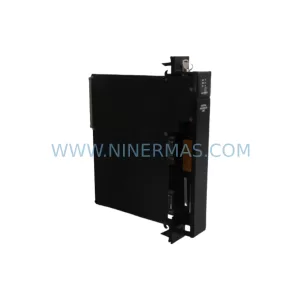
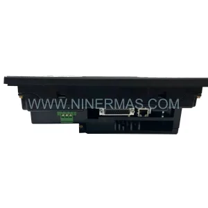
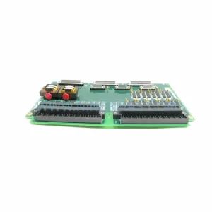
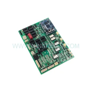
SKU: IS200AEPAH1AHD(IS215AEPAH1CA)
GE IS200AEPAH1AHD Mark VI Control Layer Module (GE) Original Spare Part RFQ
Catalog Continuation
Alternative parts within PLC & Industrial Automation Modules.
Stay inside the same system family when you need substitutes, adjacent modules, or a broader shortlist for procurement review.
SKU: 6FC5370-8AA20-0AA0
SIEMENS 6FC5370-8AA20-0AA0 Retrofit-Compatible CNC Memory
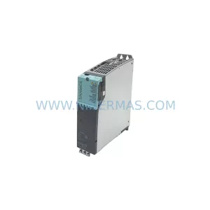
SKU: 6SL3020-2TE21-0AA4
Siemens 6SL3020-2TE21-0AA4 Service-Ready Spare Part
SKU: DX100DX200 jZRCR-YPP01-1 JZRCR-YPP21-1 SRDA-SDB95A01A-E 10Y-06A DC-24V
Yaskawa JZRCR-YPP01-1 Retrofit-Compatible Pendant for Legacy Systems