Original Industrial Spare Part
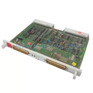
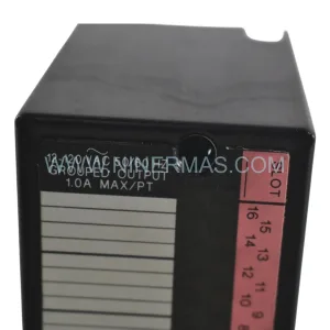
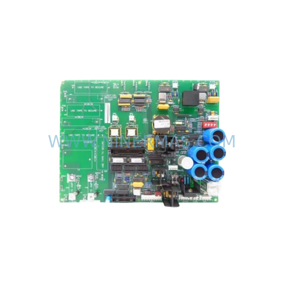
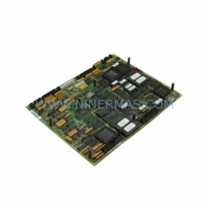
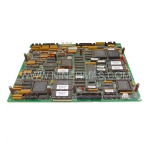
GE DS200SDCIG2ABA Retrofit-Compatible Speed Control for Legacy Systems
Verify the part, confirm the platform family, and move straight into quotation with the right commercial details.
RFQ Ready
- SKUDS200SDCIG2ABA
- CategoryPLC & Industrial Automation Modules
- BrandGE
- SupportAvailability, lead time, condition, and shipping coordination
How Buyers Usually Use This Page
- Confirm the exact part number and platform family before sending the quote request.
- Use direct email when quantity, condition, and destination are already defined internally.
- Switch to the broader brand or category archive when you need alternates nearby.
Series Navigation
Move through the most common platform families behind this part.
Product RFQ
Send this part directly for quotation.
Include quantity, required condition, destination country, and target delivery timing. Current reference: GE DS200SDCIG2ABA Retrofit-Compatible Speed Control for Legacy Systems with SKU DS200SDCIG2ABA.
GE DS200SDCIG2ABA Retrofit-Compatible Speed Control for Legacy Systems
The GE DS200SDCIG2ABA is a Speed Dynamics Control Interface board originally designed for the GE Mark V Turbine Control System. As legacy Mark V installations approach end-of-life and OEM support becomes increasingly limited, the DS200SDCIG2ABA has become a critical retrofit and replacement component for power generation facilities, petrochemical plants, and industrial turbine operators worldwide. This board governs speed sensing, dynamic control signal processing, and interface logic between the Mark V controller core and field instrumentation — making it one of the most operationally sensitive cards in the entire control cabinet.
When planning a retrofit or spare-parts replacement involving the DS200SDCIG2ABA, engineers must carefully evaluate several interdependent system parameters. Power supply compatibility is the first checkpoint: the Mark V panel typically operates on a regulated 28 VDC bus, and the SDCI board draws from this rail alongside adjacent cards such as the DS200SDCBG1ABA (Speed Control Board) and the DS200TCQBG1BHF (Turbine Control Board). Any deviation in bus voltage tolerance can cause erratic speed signal behavior or false trip conditions.
Terminal wiring is equally critical. The DS200SDCIG2ABA interfaces with magnetic pickup units (MPUs) and proximity probes through dedicated terminal blocks on the Mark V I/O panel. Before removal of the legacy board, technicians should document all field wiring assignments — particularly the MPU A and MPU B differential signal pairs — and verify continuity against the original GE Speedtronic Mark V wiring diagrams. Incorrect polarity or shielding breaks on these signal lines will produce noise-induced speed errors that are difficult to diagnose after reassembly.
Backplane connector integrity is another area requiring attention. The DS200SDCIG2ABA seats into the Mark V VME-style backplane, sharing the bus with the DS200DSPCH1ABA (Digital Signal Processor) and the DS200IOCAG1ABA (I/O Controller). Backplane pins should be inspected for oxidation or mechanical damage before installing the replacement board. A damaged backplane connector can cause intermittent communication faults that mimic board failure, leading to unnecessary repeat replacements.
Module addressing within the Mark V software environment must also be confirmed. The SDCI board occupies a fixed slot assignment in the Mark V rack, and the Speedtronic application software references this slot address for speed loop calculations. If the replacement board is installed in an incorrect slot or if the rack configuration file has not been updated to reflect the hardware revision, the control system may fail to recognize the new module or generate configuration mismatch alarms. This is particularly relevant when upgrading from an earlier DS200SDCIG1 revision to the DS200SDCIG2ABA, as the firmware baseline may differ.
Program logic compatibility should be reviewed in parallel. The Mark V application code — stored on the DS200TCQBG1BHF or equivalent processor card — references speed setpoints, acceleration ramps, and overspeed trip thresholds that are tuned to the original hardware. After installing the DS200SDCIG2ABA, a full functional test of the speed control loop is recommended, including simulation of MPU signal loss, speed reference step changes, and overspeed relay actuation. This test sequence should be completed before returning the unit to automatic control.
HMI screen validation is a frequently overlooked step in Mark V retrofit projects. Operator workstations running GE’s Cimplicity or legacy Mark V HMI software display speed feedback values derived from the SDCI board’s output. After replacement, engineers should verify that speed trend displays, alarm setpoints, and trip indication graphics reflect accurate real-time values. Discrepancies between the HMI display and the actual turbine speed can indicate a scaling or calibration issue introduced during the board swap.
Communication link integrity between the DS200SDCIG2ABA and the Mark V communication processor — typically the DS200TCQBG1BHF or the DS200DSPCH1ABA — should be confirmed via the Mark V diagnostic toolset. The internal serial communication bus carries speed data to the main processor for load control and protection functions. A failed or degraded communication link will cause the Mark V to default to a safe-state speed reference, which may result in unexpected load shedding or turbine trip during commissioning.
Installation space and mechanical fit must be verified before ordering. The DS200SDCIG2ABA occupies a single slot in the standard Mark V VME rack. If the existing rack has been modified or if adjacent boards such as the DS200SDCBG1ABA or DS200IOCAG1ABA have been repositioned, slot availability should be confirmed against the current rack layout drawing. Forced installation into a partially obstructed slot can damage the backplane connector and void the warranty.
Field commissioning should follow a structured sequence: power-down the Mark V panel, remove the legacy SDCI board, inspect the backplane, seat the DS200SDCIG2ABA firmly, restore power, confirm module recognition in the Mark V diagnostic display, run the speed loop functional test, validate HMI feedback, and document the as-left configuration. This sequence minimizes downtime and reduces the risk of repeat outages caused by incomplete commissioning steps.
Downtime control is a primary concern for any Mark V retrofit. Because the DS200SDCIG2ABA is a hot-swap-incompatible board, the turbine must be taken offline for the replacement. Pre-staging the replacement board, pre-printing the wiring documentation, and pre-briefing the commissioning team on the test sequence can reduce total outage time to under four hours for experienced crews. Having a tested spare DS200SDCIG2ABA on-site before the planned outage window is strongly recommended.
Upgrade Compatibility Table
| Parameter | DS200SDCIG1 (Legacy) | DS200SDCIG2ABA (Replacement) | Notes |
|---|---|---|---|
| Backplane Interface | VME 96-pin DIN | VME 96-pin DIN | Direct mechanical fit; inspect pins before install |
| Power Supply Rail | 28 VDC regulated | 28 VDC regulated | Verify bus voltage within ±5% tolerance |
| MPU Signal Input | Differential, 2-channel | Differential, 2-channel | Rewire if shielding is degraded |
| Communication Bus | Mark V internal serial | Mark V internal serial | Confirm link integrity post-install |
| Slot Assignment | Fixed (rack-dependent) | Fixed (rack-dependent) | Confirm slot address in application config |
| Firmware Revision | Rev 1.x baseline | Rev 2.x baseline | Review speed loop tuning parameters after swap |
| HMI Compatibility | Cimplicity / Mark V HMI | Cimplicity / Mark V HMI | Validate speed display scaling post-install |
| Overspeed Trip Relay | Supported | Supported | Functional test required before return to service |
| Installation Space | 1 VME slot | 1 VME slot | Confirm slot availability in current rack layout |
| Warranty | OEM EOL — no support | 12-Month Warranty | Pre-shipment tested; includes functional verification |
Retrofit Planning for Existing Automation Systems
A successful DS200SDCIG2ABA retrofit begins well before the outage window. The planning phase should include a full audit of the Mark V rack population, identifying all boards that share the backplane with the SDCI card. In a typical Mark V turbine control cabinet, the DS200SDCIG2ABA operates alongside the DS200SDCBG1ABA speed control board, the DS200DSPCH1ABA digital signal processor, the DS200IOCAG1ABA I/O controller, and the DS200TCQBG1BHF turbine control processor. Each of these modules contributes to the speed control loop, and a failure in any one of them can produce symptoms that are incorrectly attributed to the SDCI board.
Power distribution within the Mark V cabinet is managed by dedicated power supply modules, typically the DS200PCCAG1ABA or equivalent. Before replacing the DS200SDCIG2ABA, the power supply output should be measured under load to confirm that the 28 VDC bus is stable. A marginal power supply that is within specification at light load may drop out of tolerance when the new board initializes, causing a false startup failure that delays commissioning.
Communication infrastructure between the Mark V and plant-level SCADA or DCS systems should also be reviewed. Many legacy Mark V installations use the Mark V LAN (MLAN) or a serial Modbus link to transmit speed and load data to the plant historian or DCS. The DS200SDCIG2ABA replacement does not alter the communication protocol, but the commissioning team should confirm that speed data is flowing correctly to the upstream system after the board swap. If the plant uses a protocol converter or signal isolator between the Mark V and the DCS, these devices should be included in the post-commissioning verification checklist.
I/O expansion considerations are relevant for facilities that have added field instruments since the original Mark V installation. If additional proximity probes or tachometer inputs have been wired to the SDCI terminal block, the DS200SDCIG2ABA must be confirmed to support the total channel count. Overflow I/O should be routed through a dedicated I/O expansion module rather than overloading the SDCI input channels.
Programming cable availability is a practical concern during commissioning. Access to the Mark V application software requires a compatible programming cable and a workstation running the GE Toolbox software. If the site does not have this equipment on-hand, the commissioning team will be unable to verify slot addressing or adjust speed loop parameters after the board swap. Arranging for programming cable and software access before the outage is a low-cost step that prevents high-cost delays.
Downtime Control During System Migration
Minimizing turbine downtime during a DS200SDCIG2ABA replacement requires a combination of pre-outage preparation, disciplined execution, and post-installation verification. The most effective downtime reduction strategy is to pre-test the replacement board before the outage window. Each DS200SDCIG2ABA supplied by NINERMAS undergoes pre-shipment functional testing, which confirms that the board powers up correctly, communicates on the internal bus, and produces valid speed signal outputs. This pre-shipment test eliminates the risk of discovering a defective replacement board after the turbine has already been taken offline.
Preserving the original program logic is a non-negotiable requirement. The Mark V application code should be backed up to a portable storage device before any hardware changes are made. If the DS200DSPCH1ABA or DS200TCQBG1BHF processor card is also being replaced as part of the same outage, the application code backup becomes even more critical, as a processor card replacement without a valid code backup will require a full re-engineering of the turbine control application.
Field control continuity during the outage can be maintained by placing the turbine in manual control mode and coordinating with the plant operations team to manage load dispatch manually during the replacement window. For combined-cycle plants where the gas turbine output affects steam turbine loading, the outage window should be coordinated with the steam plant operators to avoid cascading load imbalances.
Risk reduction during the board swap is achieved by following a written procedure rather than relying on technician memory. The procedure should include step-by-step wiring documentation, torque specifications for terminal block screws, backplane connector inspection criteria, and a post-installation checklist that covers power-up sequence, module recognition, speed loop functional test, HMI validation, and communication link verification. A signed and dated commissioning record should be retained for the plant maintenance file.
Retrofit Support FAQ
Q1: Is the DS200SDCIG2ABA a direct drop-in replacement for the DS200SDCIG1?
A: The DS200SDCIG2ABA is mechanically compatible with the DS200SDCIG1 slot position and uses the same VME backplane interface. However, the firmware revision differs between the two boards. After installation, the speed loop tuning parameters and slot address configuration should be verified using the GE Toolbox software to confirm that the Mark V application recognizes the new board correctly. Pre-shipment testing confirms board functionality before dispatch.
Q2: What commissioning steps are required after installing the DS200SDCIG2ABA?
A: The recommended commissioning sequence includes: (1) confirm module recognition in the Mark V diagnostic display, (2) verify MPU signal inputs at the terminal block, (3) run a speed loop functional test including overspeed relay actuation, (4) validate HMI speed display scaling, and (5) confirm communication link integrity to the plant SCADA or DCS. Total commissioning time for an experienced crew is typically two to four hours.
Q3: How do I verify terminal wiring compatibility before installing the replacement board?
A: Compare the field wiring assignments on the existing DS200SDCIG1 terminal block against the DS200SDCIG2ABA terminal layout diagram. Pay particular attention to the MPU A and MPU B differential signal pairs, shield grounding points, and any auxiliary I/O connections. If the original wiring documentation is unavailable, the terminal assignments can be traced from the Mark V panel wiring drawings or measured in-situ before the board is removed.
Q4: What warranty and supply terms apply to the DS200SDCIG2ABA?
A: Each DS200SDCIG2ABA is covered by a 12-month warranty from the date of shipment. All units undergo pre-shipment functional testing prior to dispatch. Stock availability is maintained to support urgent replacement requirements, and expedited shipping options are available for critical outage situations. For current lead times and pricing, contact the sales team directly.
| Product Series | Mark V |
|---|---|
| Country of Origin | US |
Catalog Continuation
Nearby part numbers around DS200SDC.
Use this lane when the buyer is comparing adjacent model numbers, revision-near items, or closely related spare variants within the same brand family.
Catalog Continuation
More GE modules in the catalog.
Use the brand lane to compare nearby part numbers, platform-adjacent modules, and other inquiry-ready listings before sending your final RFQ.
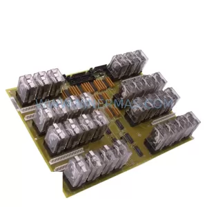
SKU: DS200SLCCG3ACC DS215DENQG3QZZ01A
GE DS200SLCCG3ACC Mark V Service-Ready Spare Part
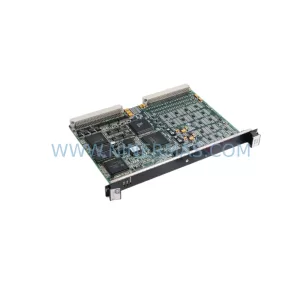
SKU: IS200VVIBH1CAB IS200VVIBH1C
GE IS200VVIBH1CAB Safety-Reliable VME Vibration Card
Catalog Continuation
Alternative parts within PLC & Industrial Automation Modules.
Stay inside the same system family when you need substitutes, adjacent modules, or a broader shortlist for procurement review.
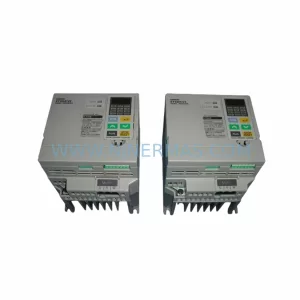
SKU: 3G3EV-AB007M-E
OMRON 3G3EV-AB007M-E Retrofit-Compatible VFD for Legacy Systems
SKU: 2711P-RDT15C SER B
Allen-Bradley 2711P-RDT15C SER B Industrial Spare Part