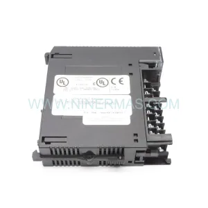
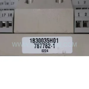
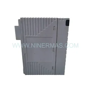
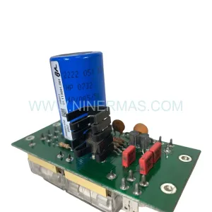
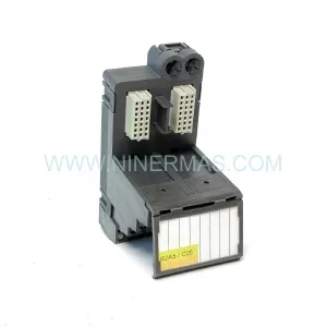
Original Industrial Spare Part
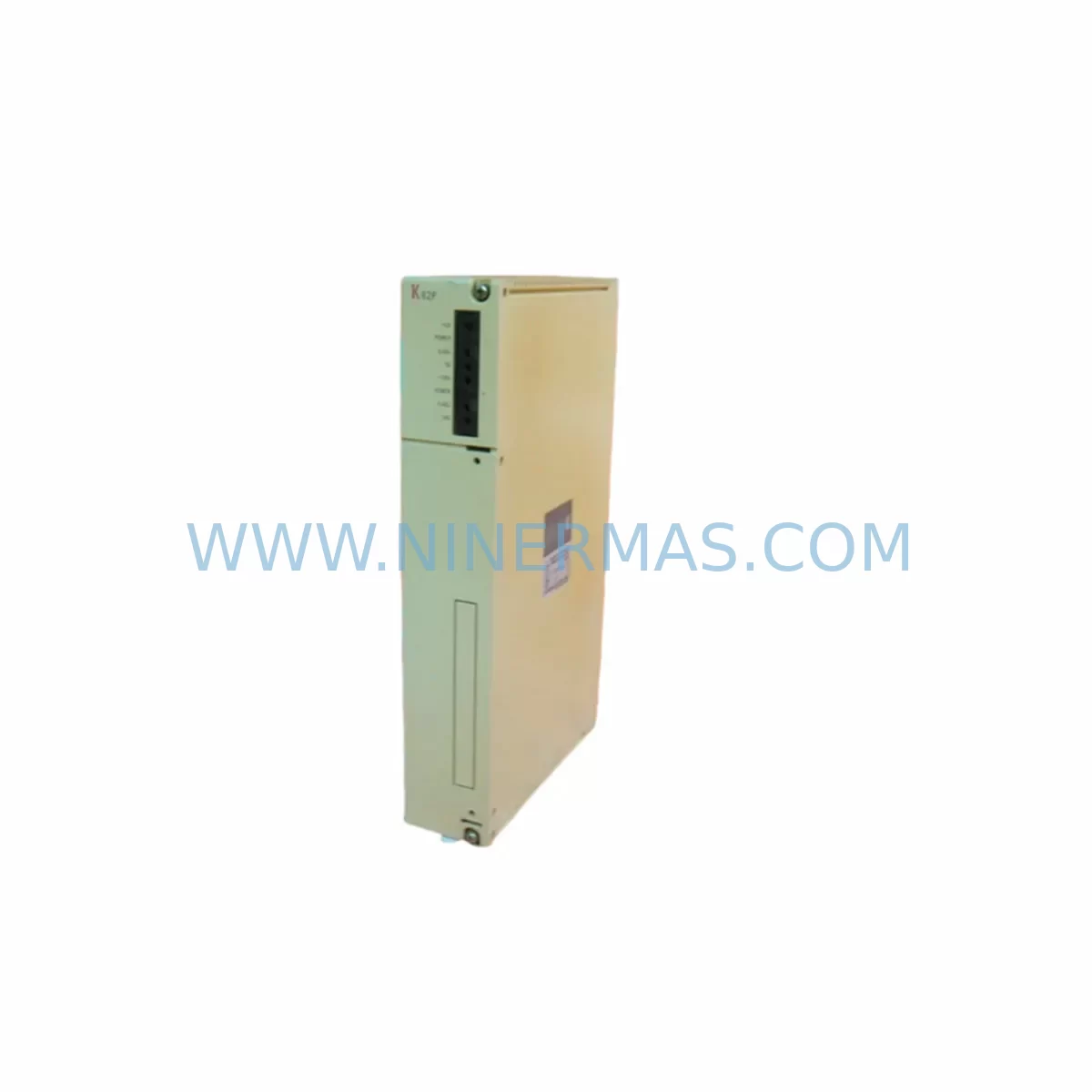
K62P Retrofit-Compatible Power Supply Module for Legacy Systems
Verify the part, confirm the platform family, and move straight into quotation with the right commercial details.
RFQ Ready
- SKUK62P
- CategoryPLC & Industrial Automation Modules
- BrandIndustrial Control Hub
- SupportAvailability, lead time, condition, and shipping coordination
How Buyers Usually Use This Page
- Confirm the exact part number and platform family before sending the quote request.
- Use direct email when quantity, condition, and destination are already defined internally.
- Switch to the broader brand or category archive when you need alternates nearby.
Series Navigation
Move through the most common platform families behind this part.
Product RFQ
Send this part directly for quotation.
Include quantity, required condition, destination country, and target delivery timing. Current reference: K62P Retrofit-Compatible Power Supply Module for Legacy Systems with SKU K62P.
K62P Retrofit-Compatible Power Supply Module for Legacy Systems
The K62P is a ruggedized, retrofit-compatible power supply module engineered for seamless integration into aging industrial control architectures. As legacy automation systems approach end-of-life, plant engineers and maintenance teams face mounting pressure to source reliable replacement components that preserve existing wiring, backplane interfaces, and program logic without triggering a full-scale system overhaul. The K62P addresses this challenge directly — delivering stable DC rail output, wide-input voltage tolerance, and a compact form factor that fits standard DIN-rail and rack-mount enclosures found in legacy control cabinets.
Whether you are replacing a failed power supply in a legacy PLC rack, upgrading an aging distributed control system (DCS) node, or consolidating power distribution across a multi-zone control cabinet, the K62P provides the electrical headroom and mechanical compatibility required to maintain production continuity. Its design accommodates the power budgets typical of older backplane assemblies, ensuring that connected I/O modules, communication modules, and CPU cards continue to operate within rated specifications after the swap.
Upgrade Compatibility Table
| Parameter | Legacy Requirement | K62P Specification | Retrofit Note |
|---|---|---|---|
| Input Voltage Range | 85–264 V AC (typical legacy) | Wide-range AC input | No transformer rewiring required in most installations |
| Output DC Rail | 24 V DC / 5 V DC (rack-dependent) | Regulated DC output | Verify backplane bus voltage before installation |
| Mounting Format | DIN-rail / rack-slot | DIN-rail compatible | Confirm slot width and depth against existing rack |
| Terminal Wiring | Screw-terminal block | Standard screw terminals | Re-use existing wire ferrules; check torque spec |
| Communication Interface | None (passive PSU) | N/A | No protocol migration required for PSU replacement |
| Backplane Connector | Legacy bus connector | Standard bus interface | Confirm pin-out compatibility with rack documentation |
| Installation Space | Varies by cabinet | Compact form factor | Measure available slot depth and width before ordering |
| Commissioning | Manual voltage check | LED status indicator | Verify output voltage under load before reconnecting I/O |
| Warranty | — | 12-Month Warranty | Covered from date of shipment; includes DOA replacement |
Retrofit Planning for Existing Automation Systems
Successful integration of the K62P into a legacy control system begins well before the module arrives on site. A structured retrofit plan reduces the risk of unexpected downtime and protects the integrity of existing program logic and field wiring.
Start by auditing the power budget of the target rack. Legacy backplane assemblies — particularly those used in older PLC chassis — distribute DC power across multiple slots simultaneously. If the rack hosts a mix of digital input modules, analog output modules, and a CPU card, the combined current draw must fall within the K62P’s rated output capacity. Document the load profile of each installed module before committing to the replacement.
Terminal block wiring is the next critical checkpoint. Many legacy control cabinets use multi-tier terminal blocks with pre-crimped wire ferrules. When removing the old power supply, label every conductor before disconnection. The K62P’s screw-terminal interface is compatible with standard ferrule sizes, but torque specifications may differ from the original unit — consult the datasheet and use a calibrated torque screwdriver during reconnection.
Backplane interface compatibility must be confirmed against the rack’s bus documentation. In systems where the power supply occupies a dedicated slot adjacent to the CPU module, the backplane connector pin-out determines whether the K62P can be inserted without an adapter plate. For racks that also house communication modules — such as PROFIBUS DP adapters, Modbus RTU gateways, or Ethernet/IP bridge cards — verify that the new power supply delivers sufficient current on the 5 V and 24 V rails to sustain all active communication links.
HMI panels connected to the control system should remain powered through an independent UPS or secondary power rail during the PSU swap. This prevents loss of operator screen data and avoids unintended alarm acknowledgements. If the HMI communicates with the PLC CPU over a serial RS-232 or RS-485 link, the communication link will be interrupted briefly during the swap — coordinate with the operations team to schedule the changeover during a planned maintenance window.
Signal isolators installed between field instruments and I/O modules are particularly sensitive to power rail fluctuations. Before energising the K62P for the first time, measure the output voltage under no-load conditions, then progressively reconnect I/O modules one rack slot at a time, monitoring the output voltage at each step. This staged commissioning approach identifies any marginal loads before they cause a nuisance trip.
Programming cables used for online monitoring — such as USB-to-serial adapters or dedicated PLC programming interfaces — should remain connected to the CPU module throughout the swap if the CPU is powered from a separate rail. This allows the maintenance engineer to monitor the PLC’s diagnostic buffer in real time and confirm that no fault codes are generated during the power supply changeover. If the CPU shares the same power rail as the K62P, a full cold-start sequence will be required after installation, and the program should be verified against the last known-good backup before returning the system to automatic mode.
For control cabinets undergoing broader modernisation — including the addition of new I/O expansion racks, replacement of legacy relay logic with solid-state output modules, or migration from proprietary fieldbus protocols to open Ethernet-based networks — the K62P provides a stable power foundation that supports incremental upgrades without requiring a simultaneous full-system replacement. This phased approach is particularly valuable in continuous-process industries where extended planned shutdowns are difficult to schedule.
Downtime Control During System Migration
Minimising unplanned downtime during a power supply replacement requires a combination of pre-work preparation, staged execution, and post-installation verification. The following practices have proven effective across a wide range of legacy system retrofit projects.
Pre-work: Obtain a full backup of the PLC program, including all data blocks, function blocks, and hardware configuration files, before beginning any physical work. Store the backup on an offline medium independent of the control system network. Confirm that the backup can be successfully restored to a spare CPU module if required.
Staged power-down: Where possible, isolate the affected rack from the broader control system before removing the old power supply. Use the system’s built-in safe-state logic to park all outputs in a known safe position. Notify upstream and downstream process areas of the impending interruption and confirm that manual overrides are in place for any safety-critical control loops.
Installation and verification: Insert the K62P into the vacated slot, reconnect all terminal wiring per the labelled documentation, and energise the module before reconnecting the backplane bus. Verify output voltage and current draw against the documented load profile. Only after confirming stable output should the backplane bus be reconnected and the CPU allowed to resume normal scan operation.
Post-installation monitoring: Monitor the system for a minimum of one full production cycle after the swap. Check the PLC diagnostic buffer for any power-related fault codes, verify that all I/O modules are communicating correctly, and confirm that HMI displays are reflecting accurate process values. Document the completed retrofit in the site’s maintenance management system, including the K62P serial number, installation date, and the name of the technician who performed the work.
Retrofit Support FAQ
Q1: Is the K62P a direct drop-in replacement for my existing power supply module?
The K62P is designed for broad retrofit compatibility with legacy industrial control racks. However, direct drop-in suitability depends on your specific rack model, backplane bus voltage, and available slot dimensions. We recommend sharing your existing module’s part number and rack documentation with our technical team before ordering so we can confirm compatibility and identify any required adapters or wiring modifications.
Q2: How is the K62P tested before shipment?
Every K62P unit undergoes a full functional test prior to dispatch. Output voltage regulation, current limiting behaviour, and input voltage tolerance are verified under load conditions. Units that do not meet specification are quarantined and not shipped. A test report is available upon request for customers who require documented evidence of pre-shipment testing for their quality management systems.
Q3: What does the 12-month warranty cover?
The 12-month warranty covers manufacturing defects and component failures under normal operating conditions from the date of shipment. It includes free-of-charge replacement or repair at our discretion. The warranty does not cover damage resulting from incorrect installation, operation outside rated specifications, physical impact, or exposure to contaminants beyond the module’s rated ingress protection class. Dead-on-arrival (DOA) units are replaced on an expedited basis.
Q4: What is your typical lead time and stock availability?
The K62P is maintained in stock for immediate dispatch. Standard orders are processed within one business day. For urgent breakdown situations, please contact our sales team directly to confirm real-time stock levels and arrange priority shipping. We maintain buffer stock specifically to support emergency spare parts requirements for legacy systems where extended lead times are not acceptable.
| Product Series | Legacy |
|---|
Catalog Continuation
More Industrial Control Hub modules in the catalog.
Use the brand lane to compare nearby part numbers, platform-adjacent modules, and other inquiry-ready listings before sending your final RFQ.
SKU: 3HAC058121-006 3HAC058121-005 IRB67003HAC058121-005
ABB 3HAC058121-006 Retrofit-Compatible Servo Unit for Legacy Systems
SKU: 20F1ANF015JN0NNNNN
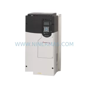
ICH 20F1ANF015JN0NNNNN Retrofit-Compatible AC Drive for Legacy Systems
Catalog Continuation
Alternative parts within PLC & Industrial Automation Modules.
Stay inside the same system family when you need substitutes, adjacent modules, or a broader shortlist for procurement review.
SKU: DS200SLCCG3ACC DS215DENQG3QZZ01A
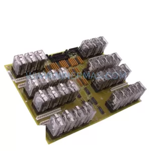
GE DS200SLCCG3ACC Mark V Service-Ready Spare Part
SKU: MPP1500D 6FC5303-1AF30-0AA0
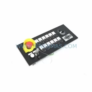
Siemens MPP1500D 6FC5303-1AF30-0AA0 Retrofit Operator Panel
SKU: 6SL3224-0BE31-5UA0
Siemens 6SL3224-0BE31-5UA0 Service-Ready Spare Part