Original Industrial Spare Part
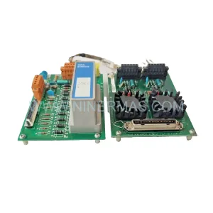
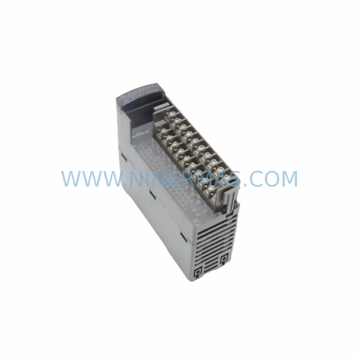
Fuji NP1Y16R-08 Retrofit Relay Output Module for Legacy Systems
Verify the part, confirm the platform family, and move straight into quotation with the right commercial details.
RFQ Ready
- SKUNP1Y16R-08
- CategoryPLC & Industrial Automation Modules
- BrandFuji Electric
- SupportAvailability, lead time, condition, and shipping coordination
How Buyers Usually Use This Page
- Confirm the exact part number and platform family before sending the quote request.
- Use direct email when quantity, condition, and destination are already defined internally.
- Switch to the broader brand or category archive when you need alternates nearby.
Series Navigation
Move through the most common platform families behind this part.
Product RFQ
Send this part directly for quotation.
Include quantity, required condition, destination country, and target delivery timing. Current reference: Fuji NP1Y16R-08 Retrofit Relay Output Module for Legacy Systems with SKU NP1Y16R-08.
Fuji NP1Y16R-08 Retrofit Relay Output Module for Legacy Systems
The Fuji NP1Y16R-08 is a 16-point relay output module designed for the Fuji Electric NP1 series programmable logic controller platform. As legacy NP1-based control systems approach end-of-life or require capacity expansion, the NP1Y16R-08 serves as a direct retrofit replacement for discontinued relay output modules within the same backplane family. Each unit undergoes pre-shipment functional testing and ships with a 12-month warranty, making it a reliable choice for maintenance engineers managing aging automation infrastructure.
Whether you are restoring a failed output card in a running production line, expanding I/O capacity in an existing NP1 control cabinet, or executing a phased modernization of a legacy relay-based system, the NP1Y16R-08 provides a compatible, low-disruption upgrade path. Its relay contact outputs support a wide range of load types including resistive, inductive, and lamp loads, making it suitable for motor starter control, solenoid valve switching, alarm annunciation, and conveyor interlock circuits.
Upgrade Compatibility Table
| Parameter | NP1Y16R-08 Specification | Retrofit Notes |
|---|---|---|
| Output Points | 16 relay contact outputs | Verify field wiring terminal count matches existing module |
| Output Type | Relay (NO contact) | Confirm load type compatibility; replace transistor output modules only after circuit review |
| Rated Load Voltage | AC 250V / DC 30V | Check existing load voltage before substitution |
| Backplane Interface | NP1 series backplane connector | Compatible with NP1 series base units and expansion racks |
| Module Address | Set via rotary switch or backplane slot | Confirm slot address matches original program I/O mapping |
| Communication Protocol | Internal NP1 backplane bus | No external protocol configuration required for local I/O |
| Installation Form Factor | Standard NP1 module width | Verify available slot space in existing control cabinet |
| Replacement Compatibility | Direct replacement for NP1Y16R series variants | Cross-reference original part number before ordering |
| Warranty | 12 months from shipment | Includes pre-shipment functional test report on request |
Retrofit Planning for Existing Automation Systems
Integrating the NP1Y16R-08 into an existing NP1 control system requires a structured pre-installation review. Begin by auditing the current backplane configuration: identify the base unit model — typically an NP1L-RS1 or NP1L-ET1 CPU module — and confirm the number of occupied and available expansion slots. If the system uses an NP1W-08ER or similar expansion rack, verify that the rack’s power budget can accommodate the additional relay output module without exceeding the internal 5V DC bus capacity.
Terminal wiring is a critical step. The NP1Y16R-08 uses a removable terminal block, which simplifies field replacement without rewiring. However, engineers should photograph or document the existing wiring layout before removal, particularly when replacing a failed module under time pressure. Cross-reference the terminal numbering against the original electrical schematic to confirm output coil assignments match the PLC program’s Y-register addressing.
For systems that also incorporate NP1X16-08 digital input modules or NP1AD04-04 analog input modules in the same rack, confirm that the total module count does not exceed the CPU’s maximum I/O point capacity. If the retrofit involves adding new output points rather than replacing a failed module, a program modification will be required — coordinate with the site’s control engineer to update the ladder logic and re-download the program using the Fuji SX-Programmer Expert or compatible programming software via the CPU’s RS-232C or USB port.
Where the NP1 system communicates upstream to a SCADA or DCS via Modbus RTU over an NP1L-RS4 serial communication module, or via Ethernet using an NP1L-ET1 module, the addition of new I/O points may require updating the Modbus register map or the SCADA tag database. Plan this configuration change during a scheduled maintenance window to avoid unintended process interruptions.
If the control cabinet also houses an NP1-HMI operator panel or a third-party HMI connected via RS-485, verify that any screen objects linked to the new output addresses are updated in the HMI project file before commissioning. Overlooking HMI screen updates is a common source of post-retrofit alarm nuisance calls.
For sites where the NP1 system interfaces with variable frequency drives, motor protection relays, or safety relay modules through the relay output contacts, confirm the contact rating of the NP1Y16R-08 is appropriate for the inrush current of the connected loads. Where loads are inductive, consider adding snubber circuits or surge suppressors across the load terminals to extend relay contact life and reduce electromagnetic interference within the control cabinet.
Downtime Control During System Migration
Minimizing unplanned downtime is the primary concern when replacing output modules in a live production environment. The NP1Y16R-08’s removable terminal block design allows the field wiring to remain connected to the terminal block while the module body is swapped, significantly reducing the time required for physical replacement. In most cases, a trained technician can complete the module exchange in under 15 minutes, provided the replacement unit has been pre-tested and the terminal block wiring has been documented in advance.
Before powering down the NP1 CPU for module replacement, upload and save a backup copy of the current PLC program using SX-Programmer Expert. Store the backup on a local engineering laptop and a network drive. This ensures that if the CPU loses its program memory during the power cycle — a risk on older NP1 units with degraded battery backup — the program can be restored immediately without waiting for the original project files to be located.
Where the process cannot tolerate a full CPU stop, consider placing the affected output points in a forced-ON or forced-OFF state using the PLC’s force table function before initiating the module swap. This maintains the last known safe state of the connected field devices during the brief period when the module is physically absent from the backplane. Confirm with the process safety engineer that forced output states are acceptable for the specific process before applying this technique.
After reinstalling the NP1Y16R-08 and restoring power, perform a point-by-point output verification using the PLC’s monitor mode: force each output coil ON individually and confirm the corresponding field device responds correctly. This structured commissioning check, combined with the pre-shipment test certification included with each NP1Y16R-08 unit, provides documented evidence of system integrity for maintenance records and regulatory compliance purposes.
Retrofit Support FAQ
Q1: Is the NP1Y16R-08 a direct drop-in replacement for other NP1 relay output modules?
The NP1Y16R-08 is designed for the Fuji NP1 series backplane and is compatible with NP1Y16R series relay output modules. Before ordering, cross-reference the original module part number against the NP1 series compatibility list to confirm pin-for-pin and address compatibility. Contact our technical team with your original part number for confirmation.
Q2: What wiring changes are required when installing the NP1Y16R-08 to replace a discontinued module?
In most cases, no wiring changes are required if the replacement module uses the same removable terminal block format. Document the existing terminal assignments before removal. If the original module used a fixed terminal block, a wiring adapter or re-termination to the NP1Y16R-08’s terminal block will be necessary. Allow additional time in the maintenance schedule for this step.
Q3: Does the NP1Y16R-08 require any program changes after installation?
If the NP1Y16R-08 is installed in the same backplane slot as the original module and the slot address is unchanged, no program modification is required. The PLC will recognize the module at the same I/O address. If the module is installed in a new slot or if I/O point expansion is the objective, the PLC program must be updated to include the new output addresses before the module is commissioned.
Q4: What does the 12-month warranty cover, and is pre-shipment testing included?
Every NP1Y16R-08 unit is functionally tested prior to shipment to verify relay contact operation, backplane communication, and output point integrity. The 12-month warranty covers manufacturing defects and functional failures under normal operating conditions. A test report is available on request. For warranty claims or technical support, contact sale@ninermas.com or call +0086 187 5021 5667.
| Product Series | Legacy |
|---|
Catalog Continuation
More Fuji Electric modules in the catalog.
Use the brand lane to compare nearby part numbers, platform-adjacent modules, and other inquiry-ready listings before sending your final RFQ.
SKU: 7500S-AZ 90130042A 80399 110M-PS
Fuji Electric 7500S-AZ Retrofit Servo Driver for Legacy Systems
Catalog Continuation
Alternative parts within PLC & Industrial Automation Modules.
Stay inside the same system family when you need substitutes, adjacent modules, or a broader shortlist for procurement review.
SKU: TRY/PRG/4-20MA/10-30DC
MOORE TRY/PRG/4-20MA/10-30DC Service-Ready Spare Part
SKU: 5085-404901-11 12INCH 2910-202413-12 404200XRMPD2H14 7-249717
TEL 5085-404901-11 Service-Ready Spare Part for Industrial Maintenance
SKU: DIP011 05-058-011
SIGMATEK DIP011 05-058-011 Service-Ready Spare Part