Original Industrial Spare Part
Fuji 6MBI75UC-120-52 Retrofit-Compatible IGBT Module
Verify the part, confirm the platform family, and move straight into quotation with the right commercial details.
RFQ Ready
- SKU6MBI75UC-120-52
- CategoryPLC & Industrial Automation Modules
- BrandFuji Electric
- SupportAvailability, lead time, condition, and shipping coordination
How Buyers Usually Use This Page
- Confirm the exact part number and platform family before sending the quote request.
- Use direct email when quantity, condition, and destination are already defined internally.
- Switch to the broader brand or category archive when you need alternates nearby.
Series Navigation
Move through the most common platform families behind this part.
Product RFQ
Send this part directly for quotation.
Include quantity, required condition, destination country, and target delivery timing. Current reference: Fuji 6MBI75UC-120-52 Retrofit-Compatible IGBT Module with SKU 6MBI75UC-120-52.
Fuji 6MBI75UC-120-52 Retrofit-Compatible IGBT Module: Legacy System Compatibility & Smooth Upgrade
The Fuji 6MBI75UC-120-52 is a 75A / 1200V six-pack IGBT module from Fuji Electric’s 6MBI UC series, widely deployed in industrial variable frequency drives (VFDs), servo amplifiers, elevator controllers, CNC spindle drives, and general-purpose inverter platforms. As original production of this module has been discontinued or supply has become increasingly constrained, plant engineers and maintenance teams across Asia, Europe, and the Americas are actively seeking verified retrofit-compatible replacements to extend the operational life of existing automation systems without committing to full drive replacement.
At NINERMAS, we specialize in sourcing, testing, and supplying hard-to-find industrial control components including the 6MBI75UC-120-52, backed by a 12-month warranty and pre-shipment functional testing. Whether you are restoring a failed drive, building a critical spare inventory, or planning a phased modernization of your control cabinet, this module is a direct retrofit candidate for your existing power stage.
Upgrade Compatibility Table
| Parameter | 6MBI75UC-120-52 Specification | Retrofit Notes |
|---|---|---|
| Collector-Emitter Voltage (VCES) | 1200V | Confirm DC bus voltage of host drive does not exceed rated VCES with derating margin |
| Continuous Collector Current (IC) | 75A | Verify load current profile; derate for ambient temperature above 25°C |
| Package Type | EconoPACK / 6-pack inline | Confirm mounting footprint, screw torque spec, and thermal interface pad thickness |
| Gate Drive Voltage | +15V / -8V (typical) | Validate gate driver board output levels before installation |
| Thermal Interface | Direct heatsink mount | Clean heatsink surface; apply fresh thermal compound; confirm flatness within 50µm |
| Communication Compatibility | N/A (power stage) | No protocol change required; upper control board remains unchanged |
| Replacement Fit | Drop-in for same footprint 6MBI UC series | Cross-reference 6MBI75U4-120 and 6MBI75UB-120 for alternate compatible variants |
| Warranty | 12 Months | Covers manufacturing defects; includes pre-shipment functional test report |
Retrofit Planning for Existing Automation Systems
Replacing the 6MBI75UC-120-52 in a live production environment requires careful pre-work to avoid secondary failures and unplanned downtime. The following planning checklist reflects real-world retrofit experience across elevator drive panels, injection molding machine controllers, and textile machinery inverter cabinets.
Power Capacity Verification: Before removing the failed module, measure the DC bus capacitor bank voltage and confirm the pre-charge resistor circuit is functioning. Many legacy drives using this IGBT module also rely on a companion Fuji FRN series or equivalent control board that governs the pre-charge sequence. If the control board has also been damaged by the IGBT failure event, it must be replaced or repaired before re-energizing the new module.
Terminal Wiring and Bus Bar Inspection: The 6MBI75UC-120-52 uses a standard EconoPACK terminal layout. Inspect the P, N, U, V, and W bus bar connections for arc damage, carbon tracking, or deformation. Damaged bus bars must be replaced — do not attempt to reuse deformed copper bars, as poor contact resistance will cause localized heating and premature module failure. If the drive uses a Fuji EG series or similar modular bus bar assembly, replacement bus bar kits are available separately.
Gate Driver Board Compatibility: The gate driver board interfaces directly with the IGBT module’s gate and emitter pins. Confirm that the driver board output voltage levels match the 6MBI75UC-120-52 gate drive requirements (+15V / -8V typical). In older drive platforms, the gate driver may have been designed for an earlier 6MBI series variant with slightly different threshold voltages. If in doubt, test the gate driver output with an oscilloscope before connecting to the new module. Common companion gate driver boards in this class of drive include Fuji EP-3955C and similar driver PCBs used across the 6MBI UC and UB series platforms.
Backplane and Rack Interface: For drives using a modular rack architecture — such as those found in large-capacity elevator control panels or multi-axis CNC systems — confirm that the power module slot address and fiber optic or ribbon cable connections to the control rack are intact. In some installations, the Fuji FRENIC series control card communicates with the power stage via a dedicated interface connector; inspect this connector for pin damage before reassembly.
I/O and Signal Isolation: If the drive failure was caused by an upstream fault (e.g., motor insulation breakdown or output short circuit), the analog and digital I/O signals feeding the drive’s control board may have been exposed to transient overvoltages. Consider installing or verifying the condition of signal isolators on speed reference, torque reference, and fault output lines before returning the system to service. Signal isolators compatible with standard ±10V and 4–20mA interfaces are commonly used in this application.
HMI Screen and Parameter Backup: Before powering down the drive for module replacement, use the drive’s keypad or a PC programming tool to export the full parameter set. For drives in the Fuji FRENIC or equivalent platform, parameter backup can be performed via the FRENIC Loader software over RS-485 or USB. This ensures that motor tuning data, acceleration/deceleration ramps, PID settings, and fault history are preserved and can be reloaded after the repair without re-commissioning from scratch.
Communication Link Restoration: If the drive is integrated into a SCADA or PLC network via Modbus RTU, PROFIBUS DP, or DeviceNet, verify that the communication option card (e.g., Fuji OPC-G1-PDP or equivalent) was not damaged during the fault event. Re-establish the communication link and confirm that the PLC — which may be a Mitsubishi MELSEC Q series, Siemens S7-300, or similar legacy controller — is receiving correct drive status feedback before resuming automatic operation.
Installation Space Confirmation: The 6MBI75UC-120-52 module dimensions must be confirmed against the available mounting space in the drive chassis. In retrofit scenarios where the original module has been replaced previously with a non-standard part, the heatsink mounting holes may have been re-drilled or the thermal pad thickness may differ. Always measure the available clearance and confirm the module sits flush against the heatsink surface before applying mounting torque.
Pre-Shipment Testing and Inventory: All 6MBI75UC-120-52 units supplied by NINERMAS undergo static parameter testing (VCES, VCE(sat), gate threshold) and dynamic switching verification prior to shipment. A test report is included with each unit. For customers managing critical spare inventories, we recommend holding a minimum of two units per drive type to cover both immediate replacement and a secondary failure scenario during the warranty period.
Downtime Control During System Migration
Minimizing production downtime during an IGBT module replacement is the primary concern for maintenance engineers. The following approach has been validated across multiple retrofit projects involving the 6MBI75UC-120-52 and similar EconoPACK modules in industrial drive applications.
Parallel Preparation: Prepare the replacement module, thermal compound, torque wrench, and gate driver test equipment before taking the drive offline. Pre-stage all tools and confirm the replacement unit has passed incoming inspection. This reduces the actual drive-offline window to the minimum mechanical replacement and verification time — typically 2 to 4 hours for an experienced technician.
Program Logic Protection: The PLC or motion controller upstream of the drive retains the ladder logic or function block program independently of the drive’s parameter set. However, if the drive fault has triggered an emergency stop or safety relay, confirm that the PLC program has not entered a latched fault state that requires a manual reset sequence before the drive can be re-enabled. Document the reset procedure before beginning the physical replacement.
Phased Re-energization: After mechanical replacement, follow a phased re-energization sequence: apply control power first (24VDC or 110VAC control circuit), verify gate driver outputs with the main power disconnected, then apply main AC power with the motor disconnected, and finally reconnect the motor and perform a no-load run before returning to full production load. This sequence protects both the new module and the connected motor from a repeat fault caused by an undetected wiring error.
Field Commissioning Verification: After the no-load run, perform a loaded test at 25%, 50%, and 100% of rated current while monitoring the module heatsink temperature, output current waveform symmetry, and drive fault log. Confirm that all three output phases are balanced and that the drive is not generating nuisance overcurrent or ground fault trips before handing the system back to production.
Retrofit Support FAQ
Q1: Is the 6MBI75UC-120-52 a direct drop-in replacement for the 6MBI75U4-120 or 6MBI75UB-120?
A: The 6MBI75UC-120-52 shares the same EconoPACK footprint and electrical ratings as the 6MBI75U4-120 and 6MBI75UB-120 in most applications. However, minor differences in VCE(sat) and switching characteristics exist between UC, UB, and U4 generations. We recommend confirming gate driver compatibility before substitution. Contact our technical team for a cross-reference confirmation specific to your drive model.
Q2: What wiring checks should be performed before installing the replacement module?
A: Inspect all P, N, U, V, and W bus bar connections for arc damage or deformation. Verify gate and emitter pin connections on the driver board. Measure insulation resistance between each output phase and ground (minimum 1MΩ at 500VDC) to confirm the motor winding is not the source of the original fault. Replace any damaged wiring or connectors before re-energizing.
Q3: How do I confirm the replacement module has been tested before shipment?
A: Every 6MBI75UC-120-52 unit shipped by NINERMAS includes a pre-shipment test report documenting VCES, VCE(sat), gate threshold voltage, and leakage current measurements. The test report serial number matches the module label. If you require additional functional testing documentation, please specify this requirement at the time of order.
Q4: What is the warranty coverage and what does it include?
A: All units carry a 12-month warranty from the date of shipment, covering manufacturing defects and parameter out-of-specification failures under normal operating conditions. The warranty does not cover damage caused by incorrect installation, overvoltage events, or operation outside rated parameters. NINERMAS maintains in-stock inventory of the 6MBI75UC-120-52 to support rapid replacement under warranty claims.
| Product Series | Other series |
|---|
Catalog Continuation
More Fuji Electric modules in the catalog.
Use the brand lane to compare nearby part numbers, platform-adjacent modules, and other inquiry-ready listings before sending your final RFQ.
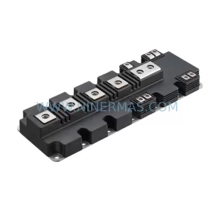
SKU: 3AXD50000711888 2MBI1400VXB-120P-50
Fuji Electric 2MBI1400VXB-120P-50 Service-Ready Spare Part
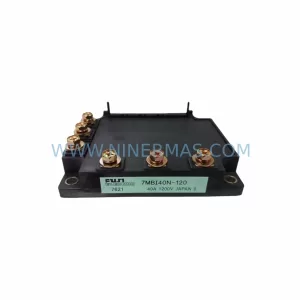
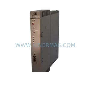
SKU: M-SPS1000RM-1F-0010-10061-0100-20003
Fuji M-SPS1000RM Retrofit Power Supply for Legacy Systems
Catalog Continuation
Alternative parts within PLC & Industrial Automation Modules.
Stay inside the same system family when you need substitutes, adjacent modules, or a broader shortlist for procurement review.
SKU: BM3401-L1OOO-AEO00CB-O-00-O-0172-000
Baumuller BM3401-L1OOO-AEO00CB-O-00-O-0172-000 Spare Part
SKU: AL203 0200-09429 V10PFT03DX2 853-200977-002
AMAT 0200-09429 Retrofit-Compatible Module for Legacy Systems