Original Industrial Spare Part
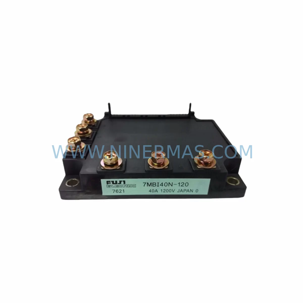
Fuji 7MBI40N-120 Retrofit IGBT Module for Legacy Systems
Verify the part, confirm the platform family, and move straight into quotation with the right commercial details.
RFQ Ready
- SKU7MBI40N-120
- CategoryPLC & Industrial Automation Modules
- BrandFuji Electric
- SupportAvailability, lead time, condition, and shipping coordination
How Buyers Usually Use This Page
- Confirm the exact part number and platform family before sending the quote request.
- Use direct email when quantity, condition, and destination are already defined internally.
- Switch to the broader brand or category archive when you need alternates nearby.
Series Navigation
Move through the most common platform families behind this part.
Product RFQ
Send this part directly for quotation.
Include quantity, required condition, destination country, and target delivery timing. Current reference: Fuji 7MBI40N-120 Retrofit IGBT Module for Legacy Systems with SKU 7MBI40N-120.
Fuji 7MBI40N-120 Retrofit IGBT Module for Legacy Systems
The Fuji Electric 7MBI40N-120 is a 6-in-1 N Series IGBT module rated at 40A / 1200V, widely deployed in legacy AC motor drives, servo amplifiers, and industrial inverter systems manufactured from the late 1990s through the 2010s. As original equipment manufacturers discontinue support for aging control platforms, the 7MBI40N-120 remains a critical retrofit and replacement component for engineers tasked with extending the operational life of existing automation infrastructure without full system replacement.
NINERMAS maintains verified stock of the 7MBI40N-120, with each unit subject to pre-shipment functional testing covering gate threshold voltage, collector-emitter saturation voltage (VCE(sat)), leakage current, and thermal resistance. A 12-month warranty is provided on all units shipped, supporting procurement teams that require documented quality assurance for safety-critical installations.
Upgrade Compatibility Table
| Parameter | 7MBI40N-120 Specification | Retrofit / Replacement Notes |
|---|---|---|
| Collector Current (IC) | 40A | Verify drive output current rating matches or exceeds 40A continuous |
| Collector-Emitter Voltage (VCES) | 1200V | Suitable for 690V AC bus systems; confirm DC link voltage does not exceed 900V under regenerative braking |
| Package Type | Fuji N Series (7-pin module) | Direct footprint replacement for 7MBI series; confirm PCB pad layout before installation |
| Gate Drive Voltage | +15V / -8V recommended | Verify existing gate driver board output levels; incompatible gate drive may cause shoot-through |
| Thermal Interface | Mounting to heatsink via M5 bolts | Apply fresh thermal compound; torque to manufacturer specification (typically 2.5–3.0 N·m) |
| Communication Compatibility | N/A (power stage component) | Upper-level control logic (PLC, DSP, FPGA) remains unchanged; only power stage is replaced |
| Replacement Recommendation | Direct drop-in for 7MBI40N-120 | Cross-reference with 7MBI50N-120 if higher current margin is required |
| Commissioning Focus | Gate signal integrity, deadtime, thermal runaway prevention | Oscilloscope verification of gate waveforms recommended before full-load commissioning |
| Warranty | 12 Months | Covers manufacturing defects; excludes damage from incorrect gate drive or overvoltage events |
Retrofit Planning for Existing Automation Systems
When planning a retrofit around the 7MBI40N-120, engineers must evaluate the complete power conversion stack rather than treating the IGBT module as an isolated component. In a typical legacy inverter control cabinet, the 7MBI40N-120 operates alongside a DC link capacitor bank, a gate driver board, a braking resistor circuit, and a control board running the PWM modulation algorithm. Replacing only the IGBT module without inspecting adjacent components introduces risk of repeat failure.
The gate driver board is the most critical adjacent component. Many legacy systems use discrete gate driver circuits built around optocoupler-based isolation, such as those found in Fuji EG series gate driver boards or third-party equivalents. Before installing the 7MBI40N-120, verify that the gate driver output voltage levels, propagation delay, and short-circuit protection response time are within the module’s datasheet requirements. If the existing gate driver board shows signs of aging — discolored PCB, swollen electrolytic capacitors, or erratic output — replacement with a compatible gate driver module is strongly recommended before powering the new IGBT.
DC link capacitors are another common failure point in aging inverter systems. Electrolytic capacitors used in the DC bus filter degrade over time, increasing equivalent series resistance (ESR) and reducing capacitance. High ESR in the DC link increases voltage ripple across the IGBT module during switching transitions, accelerating thermal stress. When retrofitting the 7MBI40N-120 into a system that has been in service for more than eight years, a concurrent DC link capacitor replacement — using appropriately rated snap-in or screw-terminal electrolytic capacitors — is advisable.
In systems where the 7MBI40N-120 is used in a three-phase full-bridge inverter topology, the braking chopper circuit and associated braking resistor must also be inspected. The braking IGBT, often a discrete module such as the Fuji 1MBI50N-120 or a similar single-switch module, handles regenerative energy dissipation. A failed braking circuit can cause DC bus overvoltage during deceleration, which may destroy a newly installed IGBT module within minutes of commissioning.
For systems integrating a PLC-based supervisory controller — such as legacy Siemens S5 or S7-300 series controllers, or Mitsubishi MELSEC A-series PLCs — the retrofit of the power stage does not require any changes to the control program. The 7MBI40N-120 replacement is transparent to the upper-level control logic, provided the PWM interface signals from the control board remain within specification. However, if the retrofit is part of a broader system modernization that includes migrating from an older PLC platform to a current-generation controller, I/O mapping and program conversion must be completed and verified before the new power stage is commissioned.
HMI screens connected to the drive system via RS-485 Modbus or PROFIBUS DP should be tested after the retrofit to confirm that drive status registers, fault codes, and parameter displays are functioning correctly. A change in the power stage does not alter the communication protocol, but a drive firmware update — sometimes required when replacing a complete drive unit rather than just the IGBT module — may shift register addresses and require HMI screen updates.
Installation space confirmation is essential in compact control cabinets. The 7MBI40N-120 uses the standard Fuji N Series footprint, but the heatsink assembly, bus bar connections, and snubber capacitor placement must be verified against the available clearance. In retrofit scenarios where the original heatsink is reused, inspect the heatsink surface for corrosion, warping, or residual thermal compound contamination before mounting the new module.
Downtime Control During System Migration
Minimizing unplanned downtime during an IGBT module replacement requires a structured pre-shutdown preparation process. Before taking the system offline, document all drive parameters — including carrier frequency, acceleration/deceleration ramps, current limits, and fault thresholds — using the drive’s parameter backup function or a handheld programmer. For legacy drives without a built-in parameter copy function, manual transcription to a commissioning sheet is necessary.
Isolate the drive from the AC supply and DC bus, then discharge the DC link capacitors fully before touching any internal components. Use a calibrated DC voltmeter to confirm that the DC bus voltage has dropped below 50V before proceeding. Failure to discharge the capacitors is a leading cause of technician injury during inverter maintenance.
Remove the failed 7MBI40N-120 by disconnecting the gate signal connector, emitter sense wire, and power terminals in sequence. Inspect the PCB pads and bus bar contact surfaces for arc damage or carbon tracking. Clean the heatsink mounting surface, apply fresh thermal interface material, and install the replacement module. Reconnect all terminals in reverse order, torquing power connections to specification.
Before applying power, perform a static gate drive test using a low-voltage bench supply to verify that all six gate channels respond correctly. This step catches wiring errors and gate driver faults before full DC bus voltage is applied. Once static testing is complete, restore drive parameters from the backup, apply power, and run the drive at reduced load for a minimum of 30 minutes while monitoring heatsink temperature and output current waveforms. A structured commissioning log — recording temperatures, currents, and any fault events — provides documentation for the 12-month warranty period and supports future maintenance planning.
Retrofit Support FAQ
Q1: Is the 7MBI40N-120 a direct replacement for the 7MBI40N-060?
No. The 7MBI40N-120 is rated for 1200V VCES, while the 7MBI40N-060 is rated for 600V. These modules are not interchangeable. Using a 600V module in a 1200V application will result in immediate failure. Always verify the voltage rating before ordering a replacement.
Q2: What pre-shipment testing does NINERMAS perform on the 7MBI40N-120?
Each unit undergoes functional testing covering gate threshold voltage, VCE(sat) at rated current, collector-emitter leakage current (ICES), and thermal resistance verification. Test results are available upon request and support quality documentation requirements for regulated industries.
Q3: Can the 7MBI40N-120 be used in a system originally designed for a different IGBT brand?
Yes, provided the electrical parameters — collector current, voltage rating, package footprint, and gate drive requirements — are compatible. The 7MBI40N-120 is a standard N Series module and can replace functionally equivalent modules from other manufacturers if the PCB layout and gate drive circuit are compatible. Consult the datasheet and verify all parameters before installation.
Q4: What is the lead time and inventory availability for the 7MBI40N-120?
NINERMAS maintains reserved stock of the 7MBI40N-120 to support urgent retrofit and breakdown replacement requirements. Standard lead time for in-stock units is 3–5 business days for international shipment. For projects requiring multiple units or long-term supply commitments, contact our sales team to discuss reserved inventory arrangements and volume pricing.
| Product Series | Legacy |
|---|
Catalog Continuation
More Fuji Electric modules in the catalog.
Use the brand lane to compare nearby part numbers, platform-adjacent modules, and other inquiry-ready listings before sending your final RFQ.
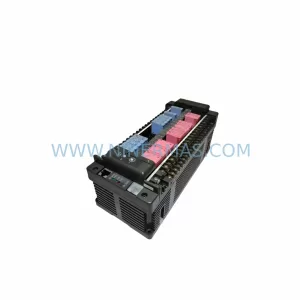
Catalog Continuation
Alternative parts within PLC & Industrial Automation Modules.
Stay inside the same system family when you need substitutes, adjacent modules, or a broader shortlist for procurement review.

SKU: 6FC5370-6AA30-0WA0
Siemens 6FC5370-6AA30-0WA0 Service-Ready Spare Part
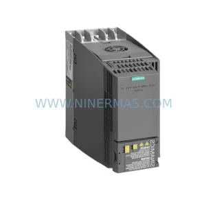
SKU: 6SL3760-0HF00-0AA1
Siemens 6SL3760-0HF00-0AA1 Retrofit Chopper Module
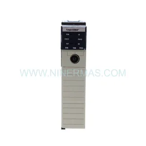
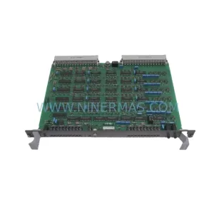
SKU: HIEE400109R0001 CSA465 AE01
ABB HIEE400109R0001 CSA465 AE01 Service-Ready Spare Part