Original Industrial Spare Part
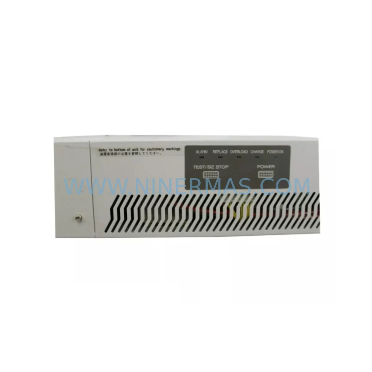
Fuji M-SPS1000RM Retrofit Power Supply for Legacy Systems
Verify the part, confirm the platform family, and move straight into quotation with the right commercial details.
RFQ Ready
- SKUM-SPS1000RM-1F-0010-10061-0100-20003
- CategoryPLC & Industrial Automation Modules
- BrandFuji Electric
- SupportAvailability, lead time, condition, and shipping coordination
How Buyers Usually Use This Page
- Confirm the exact part number and platform family before sending the quote request.
- Use direct email when quantity, condition, and destination are already defined internally.
- Switch to the broader brand or category archive when you need alternates nearby.
Series Navigation
Move through the most common platform families behind this part.
Product RFQ
Send this part directly for quotation.
Include quantity, required condition, destination country, and target delivery timing. Current reference: Fuji M-SPS1000RM Retrofit Power Supply for Legacy Systems with SKU M-SPS1000RM-1F-0010-10061-0100-20003.
Fuji M-SPS1000RM Retrofit Power Supply for Legacy Systems: Seamless Compatibility for Aging MICREX-SX Automation Infrastructure
The Fuji Electric M-SPS1000RM (order code: M-SPS1000RM-1F, part references 0010-10061 / 0100-20003) is a rack-mount power supply module engineered for the MICREX-SX programmable controller platform. As Fuji Electric progressively phases out legacy MICREX-SX hardware, maintenance engineers and system integrators face increasing pressure to source verified replacement units that can be installed without re-engineering the entire control cabinet. This module addresses that challenge directly — providing a retrofit-compatible power supply solution that preserves existing backplane wiring, rack geometry, and PLC program logic while restoring full system operability.
Whether you are managing a food processing line, a paper mill drive system, a water treatment facility, or a discrete manufacturing cell, the M-SPS1000RM delivers the stable DC bus voltage required to sustain continuous operation of MICREX-SX CPU modules, I/O racks, and communication interfaces. Every unit supplied by NINERMAS undergoes pre-shipment functional testing and is covered by a 12-month warranty from the date of delivery.
Upgrade Compatibility Table
| Parameter | Detail |
|---|---|
| Compatible Platform | Fuji Electric MICREX-SX Series PLC |
| Module Type | Rack-Mount Power Supply (SPS) |
| Primary SKU | M-SPS1000RM / Order Code: 1F-0010-10061-0100-20003 |
| Backplane Interface | Direct slot insertion into MICREX-SX base rack (NP1BP-08 / NP1BP-16 compatible) |
| Installation Requirement | No additional wiring adapter required; terminal block layout matches legacy footprint |
| Communication Compatibility | Supports co-rack operation with NP1L-RS1 (RS-232C), NP1L-RS4 (RS-485), and FL-net communication modules |
| Replacement Recommendation | Direct drop-in for end-of-life M-SPS1000RM units; verify input voltage range before installation |
| Commissioning Notes | Confirm module address DIP switch settings match original configuration; re-download PLC program if CPU memory was cleared |
| Pre-Shipment Testing | Full functional load test performed on every unit |
| Warranty | 12 months from date of delivery |
Retrofit Planning for Existing Automation Systems
Replacing a power supply module in an active MICREX-SX control system requires careful pre-work to avoid unplanned downtime and configuration loss. The M-SPS1000RM slots into the same rack position as the original unit, but engineers should verify several interdependent system elements before proceeding.
Begin with a full audit of the control cabinet’s power budget. The MICREX-SX rack may be populated with a combination of NP1X1606-W 16-point DC digital input modules, NP1Y1606-W 16-point transistor output modules, and NP1AX08-W analog input modules. Each of these draws current from the rack bus, and the aggregate load must remain within the M-SPS1000RM’s rated output capacity. If the rack has been expanded since original commissioning — for example, by adding NP1S-11 special function modules or additional NP1L-RS4 communication cards — recalculate the power budget before installation.
Next, inspect the backplane. The NP1BP-08 (8-slot) and NP1BP-16 (16-slot) base racks used in MICREX-SX installations have a fixed power supply slot at the leftmost position. The M-SPS1000RM occupies this slot exclusively and connects to the backplane bus via a direct edge connector — no ribbon cable or intermediate adapter is involved. Confirm that the backplane connector pins are clean and undamaged before inserting the replacement module.
Terminal block wiring on the AC input side should be documented before removal of the failed unit. Photograph or sketch the existing wiring, noting the L, N, and PE (protective earth) connections. The M-SPS1000RM uses a standard screw-terminal input block; wire gauge and torque specifications should be observed to maintain compliance with local electrical codes.
If the system includes an NP1PS-74 CPU module or similar MICREX-SX processor, verify that the CPU’s battery-backed RAM has retained the PLC program. In cases where the power supply failure caused a complete loss of rack voltage, the CPU memory may have been corrupted. Have the original program file available on a programming laptop with the MICREX-SX programming software loaded, along with the appropriate FPU programming cable, so that a program re-download can be performed immediately after power restoration if needed.
For systems that use FL-net or OPCN-1 field network communication, confirm that the NP1L-RS1 or equivalent communication module retains its node address and baud rate settings after the power cycle. Some communication modules store configuration in non-volatile memory; others revert to factory defaults on power loss. This step is critical in multi-drop network topologies where a misconfigured node address can disrupt the entire field bus segment.
HMI panels connected to the MICREX-SX system — whether Fuji Electric V-series touch panels or third-party SCADA terminals — should be checked for communication link restoration after the new power supply is energized. Confirm that the HMI screen data and tag mappings are intact and that the communication driver reconnects automatically without requiring a manual restart of the HMI application.
Finally, confirm physical installation clearances. The M-SPS1000RM requires adequate ventilation space above and below the module in the control cabinet. If the cabinet has been retrofitted with additional components since original installation, verify that airflow paths have not been obstructed, as thermal management directly affects the long-term reliability of the power supply and adjacent modules including signal isolators and analog I/O cards.
Downtime Control During System Migration
Minimizing production downtime during a power supply replacement is a primary concern for any maintenance team. The M-SPS1000RM retrofit process is designed to be completed within a single planned maintenance window, typically two to four hours depending on system complexity and the need for program re-download.
Before the maintenance window begins, prepare a complete backup of the PLC program from the NP1PS-74 CPU or equivalent processor using the MICREX-SX programming environment. Store this backup on at least two independent media — a local laptop and a network share or USB drive. This ensures that even if the CPU memory is lost during the power transition, the program can be restored without delay.
Coordinate with production scheduling to select a maintenance window that aligns with a natural process break — shift changeover, scheduled cleaning, or a planned material changeover. Communicate the expected outage duration to all affected departments and confirm that any interlocked systems (conveyors, drives, safety relays) are placed in a safe state before cabinet power is removed.
During the swap, work methodically: isolate the AC input, discharge any residual bus capacitance, remove the failed M-SPS1000RM, inspect the backplane slot, insert the replacement unit, and restore AC power in sequence. Avoid rushing the commissioning verification steps — confirm that all I/O modules, communication cards, and the CPU module enumerate correctly on the backplane before releasing the system to production. A structured commissioning checklist reduces the risk of overlooking a misconfigured module address or a communication link that failed to reconnect automatically.
NINERMAS maintains ready stock of the M-SPS1000RM to support emergency replacement scenarios. For critical production environments, we recommend holding at least one spare unit on-site to eliminate lead time risk entirely. All units are shipped with pre-shipment test documentation and are covered by a 12-month warranty, giving your maintenance team confidence that the replacement unit will perform reliably from day one.
Retrofit Support FAQ
Q1: Is the M-SPS1000RM a direct replacement for the original Fuji Electric unit, or are there wiring or configuration changes required?
The M-SPS1000RM is designed as a direct drop-in replacement for the original MICREX-SX power supply module of the same part number. The terminal block layout, backplane connector, and rack slot dimensions are identical to the original. No wiring adapters or configuration changes are required in the majority of installations. However, engineers should verify the input voltage range (100–240 VAC or fixed 200 VAC depending on variant) matches the site supply before installation.
Q2: What commissioning steps are required after installing the replacement power supply?
After installing the M-SPS1000RM and restoring AC power, confirm that all modules on the backplane — including CPU, digital I/O, analog I/O, and communication modules — are recognized by the system. Check the CPU status LEDs and any diagnostic indicators on the NP1L-RS1 or NP1L-RS4 communication modules. If the CPU program was lost during the failure event, re-download the program from your backup file using the MICREX-SX programming software and the appropriate FPU programming cable. Verify HMI communication link restoration before returning the system to automatic mode.
Q3: Does NINERMAS provide pre-shipment testing documentation for the M-SPS1000RM?
Yes. Every M-SPS1000RM unit supplied by NINERMAS undergoes a full functional load test prior to shipment. Test documentation confirming output voltage stability, load regulation, and ripple performance is available upon request. All units are covered by a 12-month warranty from the date of delivery, and our technical team is available to support commissioning queries.
Q4: What is the typical lead time, and can NINERMAS support emergency orders?
NINERMAS maintains inventory of the M-SPS1000RM to support both planned procurement and emergency replacement scenarios. Standard orders are processed and shipped within 3–5 business days. For urgent requirements, please contact our sales team directly at sale@ninermas.com or +0086 187 5021 5667 to confirm current stock availability and expedited shipping options.
| Product Series | Legacy |
|---|
Catalog Continuation
More Fuji Electric modules in the catalog.
Use the brand lane to compare nearby part numbers, platform-adjacent modules, and other inquiry-ready listings before sending your final RFQ.
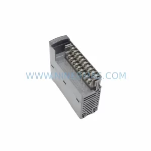
Catalog Continuation
Alternative parts within PLC & Industrial Automation Modules.
Stay inside the same system family when you need substitutes, adjacent modules, or a broader shortlist for procurement review.
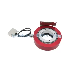
SKU: E19299450 E19299451 W/ MERCURY II 6000 ME-88-Y233-1 PCA-28430
Varian E19299450/E19299451 Service-Ready Spare Part
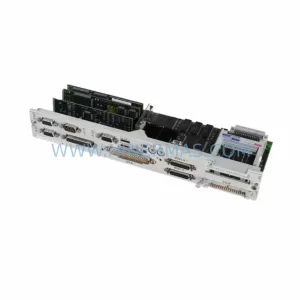
SKU: 6FC5357-0BB11-0AE1
Siemens 6FC5357-0BB11-0AE1 Retrofit NCU for Legacy Systems
SKU: 6SL3210-1PE34-8CL0
SIEMENS 6SL3210-1PE34-8CL0 Service-Ready Spare Part