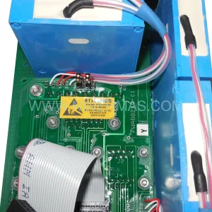
Original Industrial Spare Part
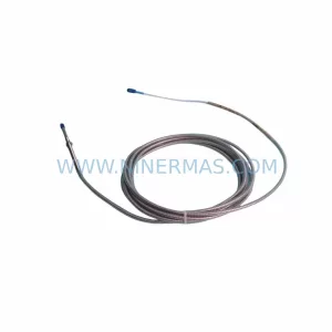
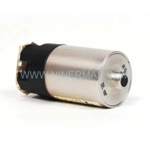
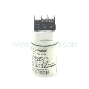
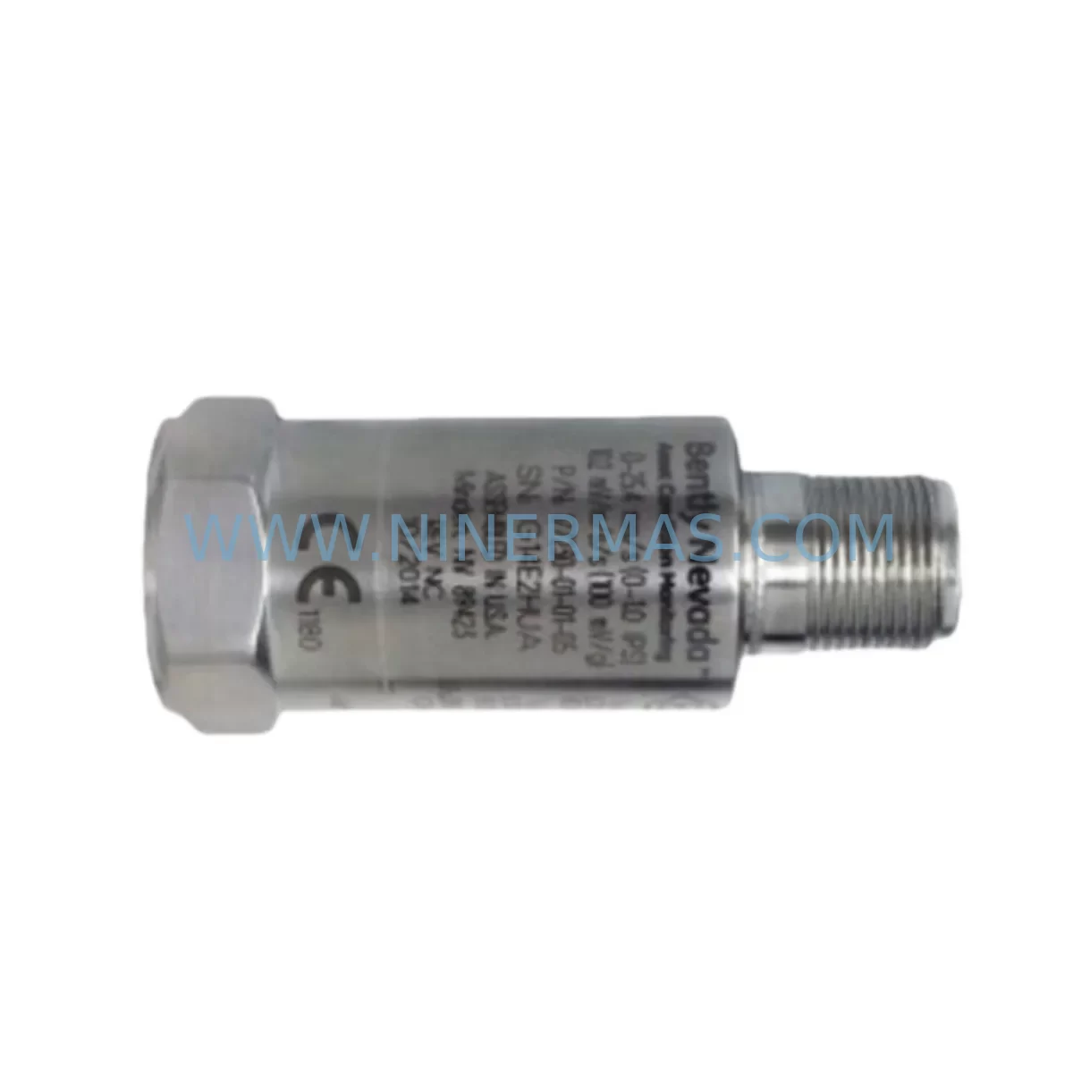
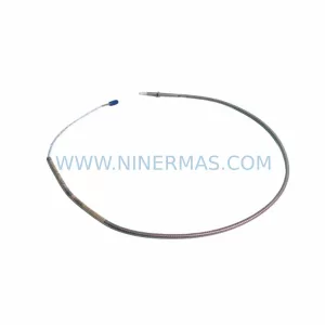
Bently Nevada 190501-23-00-CN Retrofit Velomitor CT Velocity Transducer
Verify the part, confirm the platform family, and move straight into quotation with the right commercial details.
RFQ Ready
- SKU190501-23-00-CN
- CategoryTSI & Rotating Machinery Monitoring
- BrandBently Nevada
- SupportAvailability, lead time, condition, and shipping coordination
How Buyers Usually Use This Page
- Confirm the exact part number and platform family before sending the quote request.
- Use direct email when quantity, condition, and destination are already defined internally.
- Switch to the broader brand or category archive when you need alternates nearby.
Series Navigation
Move through the most common platform families behind this part.
Product RFQ
Send this part directly for quotation.
Include quantity, required condition, destination country, and target delivery timing. Current reference: Bently Nevada 190501-23-00-CN Retrofit Velomitor CT Velocity Transducer with SKU 190501-23-00-CN.
Bently Nevada 190501-23-00-CN Retrofit Velomitor CT Velocity Transducer: Legacy System Compatibility & Smooth Upgrade
The Bently Nevada 190501-23-00-CN is a Velomitor CT piezo-velocity transducer engineered for high-frequency vibration measurement in rotating machinery applications. As a retrofit-compatible replacement for legacy Bently Nevada monitoring systems, this unit supports direct integration into existing control architectures without requiring full panel redesign. Whether you are managing a planned upgrade cycle or responding to an unplanned failure of a discontinued sensor, the 190501-23-00-CN delivers the signal fidelity and mechanical compatibility your system demands.
This transducer is widely deployed in turbine monitoring, compressor protection, pump vibration analysis, and motor bearing surveillance. Its integrated electronics output a velocity signal (mV/mm/s or mV/in/s) compatible with the Bently Nevada 3300 Series, 3500 Series, and ADRE-based monitoring platforms. Engineers retrofitting older 330500 or 330525 proximity probe systems often select the 190501-23-00-CN as a complementary or replacement sensor where proximity probes are no longer practical due to shaft geometry changes or housing constraints.
Upgrade Compatibility Table
| Parameter | 190501-23-00-CN Specification | Retrofit Notes |
|---|---|---|
| Sensor Type | Piezo-velocity (Velomitor CT) | Direct replacement for legacy velocity transducers in BN monitoring racks |
| Output Signal | Integrated velocity output (mV/mm/s) | Compatible with 3300 XL 11mm and 3500/42M velocity monitor cards |
| Frequency Range | 2 Hz – 2,000 Hz | Covers low-speed and high-speed machinery; verify against existing monitor card input range |
| Connector / Termination | 2-pin MIL-spec connector | Check existing cable assembly; adapter cables may be required for older installations |
| Mounting | 1/4-28 UNF threaded stud | Confirm bearing housing thread; stud adapters available for metric housings |
| Power Supply | 18–30 VDC (loop powered) | Verify power supply capacity in existing junction box or marshalling cabinet |
| Communication Protocol | Analog 4–20 mA / voltage output | No protocol migration required; direct wiring to existing BN monitor inputs |
| Installation Space | Standard BN transducer footprint | Confirm clearance at bearing cap; no panel cutout modification required |
| Warranty | 12 Months | Covered from date of shipment; includes functional and output accuracy verification |
| Replacement Recommendation | Replaces 190501-23-00, 190501-01-00-CN variants | Confirm suffix compatibility with monitor card firmware revision |
Retrofit Planning for Existing Automation Systems
Successful integration of the 190501-23-00-CN into a legacy monitoring system requires a structured pre-installation review. Before removing the existing sensor, engineers should document the current wiring scheme at the field junction box, noting terminal polarity, shield grounding practice, and cable routing. The Bently Nevada 3500/42M Velocity Monitor or 3300 XL 11mm Velocity Monitor card must be confirmed as the receiving device, and the channel configuration within System 1 or ADRE 408 DSPi software should be reviewed to ensure the engineering unit scaling matches the new transducer’s sensitivity specification.
In installations where the 190501-23-00-CN replaces a seismic velocity sensor on a steam turbine or gas compressor train, the technician should also verify the 3500 rack’s power supply module — typically the 3500/15 Power Supply — is delivering stable 24 VDC to the transducer loop. Voltage sag under full rack load is a common cause of signal drift after sensor replacement. If the rack also houses 3500/22M Transient Data Interface or 3500/40M Proximitor Monitor cards, confirm that the rack’s total current draw remains within the power supply’s rated output after adding the new transducer loop.
For plants running older 3300 Series racks, the retrofit may also involve replacing the 3300/16 Velocity Monitor card with a current-production equivalent. In these cases, the 190501-23-00-CN is typically installed alongside a new monitor card, and the technician must re-enter alarm setpoints, full-scale ranges, and danger bypass configurations. If the plant uses a Bently Nevada TDXnet or System 1 data concentrator, the new channel must be mapped in the software before the sensor is energized.
Plants operating mixed fleets — where some machines use proximity probes (330500, 330525, or 330180 series) and others use velocity transducers — should pay particular attention to the marshalling cabinet layout. The 190501-23-00-CN’s two-conductor shielded cable must be routed away from high-voltage power cables to prevent induced noise. A signal isolator or Bently Nevada 3500/20 Rack Interface I/O Module may be required if the existing cable run exceeds 300 meters or passes through electrically noisy environments such as variable frequency drive (VFD) enclosures.
Where the retrofit involves a DCS or safety system integration, the analog output of the 190501-23-00-CN feeds into the 3500 rack’s relay output module (3500/32 or 3500/33), which in turn drives the plant’s emergency shutdown logic. Confirm that the relay contact ratings and trip delay settings are preserved during the card swap. If the plant’s safety instrumented system (SIS) requires proof-test documentation, the 190501-23-00-CN’s factory calibration certificate and functional test report should be retained for the SIS maintenance record.
Downtime Control During System Migration
Minimizing production downtime during a velocity transducer replacement requires advance preparation and a clear handover protocol between the instrumentation team and the control room operator. The recommended approach is to place the affected monitor channel into bypass mode within the 3500 rack before disconnecting the old sensor. This prevents a spurious trip signal from reaching the emergency shutdown system while the transducer is open-circuit during the swap.
The original program logic in the DCS or PLC — including any Modbus or OPC-DA tags mapped to the vibration channel — should be documented before the work begins. If the plant uses a Bently Nevada System 1 historian, the channel tag name and engineering unit configuration should be exported and saved. After the 190501-23-00-CN is installed and wired, the technician should perform a bench-level functional check using a calibrated shaker or signal simulator before re-energizing the loop in the field. This step confirms that the transducer’s sensitivity and frequency response are within specification before the bypass is removed.
For critical machinery where continuous monitoring is contractually required, a temporary portable vibration analyzer — such as a CSI 2140 or equivalent — can be clamped to the bearing housing to maintain surveillance during the swap window. This approach is particularly valuable on single-train compressors or turbines where no redundant monitoring path exists. Once the 190501-23-00-CN is confirmed operational and the 3500 rack channel is back in service, the portable analyzer data should be compared against the new permanent channel reading to validate consistency before the bypass is cleared.
Post-installation, the technician should trend the new sensor’s output for a minimum of 24 hours under normal operating conditions before closing the work order. Any deviation from the pre-replacement baseline — particularly at running speed (1X) or twice running speed (2X) — should be investigated before the machine is returned to full load. This discipline protects both the equipment and the integrity of the plant’s condition monitoring program.
Retrofit Support FAQ
Q: Is the 190501-23-00-CN a direct drop-in replacement for the 190501-23-00 (without the -CN suffix)?
A: In most applications, yes. The -CN suffix denotes a configuration variant, typically related to connector type or cable termination. Confirm the connector pinout and cable assembly compatibility before installation. If the existing cable uses a different MIL-spec shell size, a field-wireable adapter is available.
Q: What commissioning steps are required after installation?
A: After wiring, verify DC bias voltage at the monitor card input (typically 8–12 VDC for a healthy Velomitor CT loop). Confirm the channel is reading a plausible vibration level at machine idle speed. Check alarm and danger setpoints in the 3500 rack configuration software and validate that the relay outputs respond correctly to a simulated over-vibration condition before removing bypass.
Q: Has this unit been tested before shipment?
A: Yes. Each 190501-23-00-CN unit undergoes functional output verification and sensitivity calibration prior to dispatch. A test report is available upon request. Units are shipped in anti-static packaging with protective connector caps to prevent transit damage.
Q: What is the warranty coverage and what does it include?
A: All units carry a 12-month warranty from the date of shipment. The warranty covers manufacturing defects, output accuracy out-of-specification conditions, and connector integrity. It does not cover damage resulting from incorrect wiring, over-voltage conditions, or mechanical impact. Warranty claims are processed within 5 business days of receipt of the returned unit.
—
| Product Series | 3300 series |
|---|---|
| Country of Origin | US |
Catalog Continuation
More Bently Nevada modules in the catalog.
Use the brand lane to compare nearby part numbers, platform-adjacent modules, and other inquiry-ready listings before sending your final RFQ.
SKU: 330704-000-060-10-02-CN
Bently Nevada 330704-000-060-10-02-CN 3300 XL Probe
SKU: 31000-00-00-00-070-03-02
Bently Nevada 31000-00-00-00-070-03-02 Service-Ready Spare Part for Industrial Maintenance
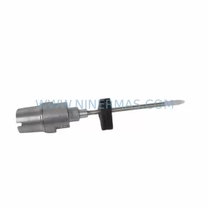
SKU: 21000-28-10-00-167-04-02
Bently Nevada 21000-28-10-00-167-04-02 Retrofit Proximity Probe
Catalog Continuation
Alternative parts within TSI & Rotating Machinery Monitoring.
Stay inside the same system family when you need substitutes, adjacent modules, or a broader shortlist for procurement review.
SKU: 330880-16-15-020-01-02
Bently Nevada 330880-16-15-020-01-02 Service-Ready Spare Part
SKU: 330910-00-13-10-02-05
Bently Nevada 330910-00-13-10-02-05 Safety-Reliable Proximity Transducer