Original Industrial Spare Part
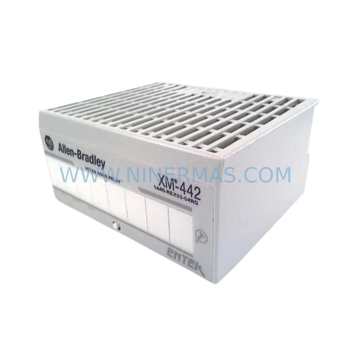
Allen-Bradley 1440-REX03-04RG XM Series Spare Part
Verify the part, confirm the platform family, and move straight into quotation with the right commercial details.
RFQ Ready
- SKU1440-REX03-04RG
- CategoryTSI & Rotating Machinery Monitoring
- BrandAllen-Bradley
- SupportAvailability, lead time, condition, and shipping coordination
How Buyers Usually Use This Page
- Confirm the exact part number and platform family before sending the quote request.
- Use direct email when quantity, condition, and destination are already defined internally.
- Switch to the broader brand or category archive when you need alternates nearby.
Series Navigation
Move through the most common platform families behind this part.
Product RFQ
Send this part directly for quotation.
Include quantity, required condition, destination country, and target delivery timing. Current reference: Allen-Bradley 1440-REX03-04RG XM Series Spare Part with SKU 1440-REX03-04RG.
Allen-Bradley 1440-REX03-04RG XM Series Service-Ready Spare Part for Industrial Maintenance
The Allen-Bradley 1440-REX03-04RG is a relay expansion module within the Rockwell Automation XM Series dynamic measurement platform, engineered for continuous vibration monitoring and machine protection in demanding industrial environments. As a service-ready spare part, this module is stocked, tested, and ready for immediate deployment to minimize unplanned downtime and restore control system integrity during scheduled or emergency maintenance events.
For maintenance engineers managing rotating machinery protection systems, the 1440-REX03-04RG provides relay output expansion capability for the XM Series monitoring architecture. It integrates directly with XM Series dynamic measurement modules such as the 1440-DYN02-01RJ accelerometer input module and the 1440-VST02-01RA standard dynamic measurement module, extending the relay output capacity of the monitoring rack without requiring additional controller resources. When replacing this module, engineers should also inspect the associated 1440-TB-A terminal base, which serves as the mounting and wiring interface for all XM Series modules. Verifying terminal base condition and wiring integrity before installing a replacement relay expansion module is a critical step in any maintenance workflow.
The XM Series platform communicates over DeviceNet, and during any relay module replacement, the DeviceNet node address and baud rate settings must be confirmed and matched to the existing network configuration. If the control system includes a 1440-ACNR15-04S ControlNet adapter or a 1756-DNB DeviceNet scanner module in the ControlLogix backplane, the replacement module must be re-commissioned within the network scan list to restore full communication. Maintenance teams should also verify that the 1756-L7x or 1756-L8x ControlLogix controller program retains the correct I/O configuration tags for the relay outputs, as any mismatch will generate faulted module status and prevent relay operation.
From a power supply perspective, the XM Series rack draws 24 VDC from a dedicated industrial power supply. Before replacing the 1440-REX03-04RG, confirm that the supply voltage is within specification and that the 1606-XLP power supply or equivalent unit feeding the monitoring rack is functioning correctly. Voltage fluctuations or ripple outside acceptable limits can cause relay module faults even after a successful hardware replacement. A 1492-SP fuse block or equivalent branch circuit protection should also be inspected to ensure the relay module’s power branch is properly protected.
In facilities running continuous production lines — including petrochemical compressor trains, power generation turbines, mining conveyor drives, and pulp and paper refiners — the 1440-REX03-04RG relay outputs are typically wired into safety interlock circuits or alarm annunciator panels. During replacement, the relay output wiring to the field terminal strip or marshalling cabinet must be documented and verified before re-energizing. If the site uses a 1715 redundant I/O system or a Safety PLC such as the 1756-L7SP GuardLogix controller, the relay outputs may be part of a safety-rated interlock loop, and any replacement must follow the site’s Management of Change (MOC) procedure and functional safety verification protocol.
For procurement engineers, maintaining a minimum stock level of the 1440-REX03-04RG is recommended for any facility operating multiple XM Series monitoring racks. The module’s role in relay output expansion makes it a single point of failure for alarm and trip output circuits, and lead times for new procurement can extend beyond acceptable downtime windows in critical applications. NINERMAS maintains verified inventory of the 1440-REX03-04RG with full pre-shipment electrical testing, ensuring that every unit shipped meets original specification before it reaches the field.
Spare Maintenance Table
| Parameter | Specification / Detail |
|---|---|
| Part Number | 1440-REX03-04RG |
| Brand / Manufacturer | Allen-Bradley / Rockwell Automation |
| Series | XM Series Dynamic Measurement |
| Module Type | Relay Expansion Module |
| Relay Outputs | 3 relay outputs (expandable) |
| Communication | DeviceNet |
| Supply Voltage | 24 VDC (nominal) |
| Mounting | XM Series Terminal Base (1440-TB-A) |
| Operating Temperature | 0°C to 60°C (32°F to 140°F) |
| Enclosure Rating | IP20 (panel mount) |
| Compatible Controllers | ControlLogix, CompactLogix, GuardLogix |
| Country of Origin | United States |
| Warranty | 12-Month Warranty — All units pre-shipment tested |
Maintenance Planning for Continuous Operation
Effective maintenance planning for XM Series-based machine protection systems requires a holistic view of the monitoring rack and its associated field wiring, power infrastructure, and communication network. When the 1440-REX03-04RG relay expansion module is identified as a failed or degraded component, the replacement process should be treated as an opportunity to inspect the entire monitoring node.
Begin with the terminal base: the 1440-TB-A terminal base should be inspected for corrosion, loose screw terminals, and damaged wiring insulation. In high-humidity or chemically aggressive environments, terminal oxidation is a common cause of intermittent relay faults that are incorrectly attributed to the module itself. If the terminal base shows signs of degradation, it should be replaced concurrently with the relay module to avoid repeat failures.
Next, verify the DeviceNet segment health. Use a DeviceNet analyzer or the RSNetWorx for DeviceNet diagnostic tool to confirm that the network segment carrying the XM Series node is operating within voltage and current specifications. A failing 1485P-P1A5-T5 DeviceNet tap or a degraded trunk cable can cause intermittent communication faults that mimic relay module failures. Replacing the module without addressing network issues will result in recurring faults.
The 1440-DYN02-01RJ dynamic measurement module connected to the same terminal base should also be checked for active faults and calibration status. If the dynamic measurement module is reporting sensor input errors from a connected accelerometer or velocity transducer, those faults may be masking relay output issues or causing nuisance relay operations. Confirm that all connected sensors — including any 4-20 mA process transmitters or proximity probes wired to the XM rack — are within calibration and producing valid signals.
For the control cabinet power distribution, inspect the 1606-XLP72E or equivalent 24 VDC power supply output voltage under load. A supply that is within specification at no load but droops under full rack load can cause relay module brownout faults. If the facility uses a redundant power supply configuration with a 1606-XLP redundancy module, verify that the redundancy module is functioning and that both supply channels are active.
Finally, review the ControlLogix program for any inhibited or faulted I/O modules in the rack. A 1756-DNB DeviceNet scanner that has lost its connection to the XM Series node will inhibit all relay outputs on the affected modules. Clearing the scanner fault and re-establishing the DeviceNet connection is required before the replacement relay module can be commissioned.
Site Replacement Workflow
Replacing the Allen-Bradley 1440-REX03-04RG in a live industrial facility requires a structured workflow to minimize downtime and ensure system compatibility. The following steps outline a best-practice replacement procedure for maintenance teams:
Step 1 — Pre-Replacement Documentation: Record all relay output wiring connections, DeviceNet node address, and current module configuration using RSNetWorx for DeviceNet or the XM Series configuration tool. Photograph the terminal wiring before disconnection.
Step 2 — Safe Isolation: Follow the site’s Lockout/Tagout (LOTO) procedure for the monitoring rack. De-energize the 24 VDC supply to the XM Series rack before removing the relay expansion module from the terminal base.
Step 3 — Module Removal and Inspection: Remove the 1440-REX03-04RG from the 1440-TB-A terminal base. Inspect the terminal base connector pins for damage or contamination. Clean if necessary before installing the replacement module.
Step 4 — Replacement Module Installation: Install the new 1440-REX03-04RG onto the terminal base. Verify that the module is fully seated and the locking mechanism is engaged.
Step 5 — Re-Energization and Communication Verification: Restore 24 VDC power to the rack. Verify that the replacement module appears on the DeviceNet network with the correct node address and that the 1756-DNB scanner recognizes the module without faults.
Step 6 — Functional Test: From the ControlLogix controller, command each relay output through its full operating cycle and verify field-side response at the connected interlock or alarm circuit. Document test results before returning the system to service.
NINERMAS ships all 1440-REX03-04RG units with pre-shipment electrical test documentation, reducing the risk of installing a non-conforming unit and shortening the on-site commissioning time.
Spare Parts Support FAQ
Q1: What is the warranty coverage for the 1440-REX03-04RG supplied by NINERMAS?
All 1440-REX03-04RG units supplied by NINERMAS carry a 12-month warranty from the date of shipment. Each unit undergoes pre-shipment electrical testing to verify relay output function, communication interface integrity, and power supply compatibility before dispatch. Warranty claims are supported with direct technical assistance and replacement unit provision.
Q2: Is the 1440-REX03-04RG compatible with all XM Series terminal bases and dynamic measurement modules?
The 1440-REX03-04RG is designed for use with the XM Series 1440-TB-A terminal base and is compatible with the full range of XM Series dynamic measurement modules, including the 1440-DYN02-01RJ and 1440-VST02-01RA. Compatibility with the existing DeviceNet network configuration should be verified by confirming node address settings and network scan list entries in the 1756-DNB scanner before commissioning.
Q3: Can NINERMAS supply the 1440-REX03-04RG for long-term or repeat procurement requirements?
Yes. NINERMAS maintains ongoing inventory of the 1440-REX03-04RG to support facilities with multiple XM Series monitoring racks and long-term maintenance contracts. Volume procurement and scheduled delivery arrangements are available to support annual maintenance planning and spare parts inventory programs.
Q4: What pre-shipment testing is performed on each 1440-REX03-04RG unit?
Each unit is tested for relay output switching function, DeviceNet communication interface response, supply voltage acceptance within the 24 VDC nominal range, and physical connector integrity. Test records are available upon request and accompany each shipment to support site acceptance testing and maintenance documentation requirements.
| Product Series | y 1440-REX03-04RG XM Series |
|---|---|
| Country of Origin | US |
Catalog Continuation
More Allen-Bradley modules in the catalog.
Use the brand lane to compare nearby part numbers, platform-adjacent modules, and other inquiry-ready listings before sending your final RFQ.
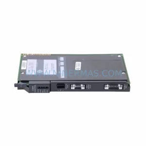
Catalog Continuation
Alternative parts within TSI & Rotating Machinery Monitoring.
Stay inside the same system family when you need substitutes, adjacent modules, or a broader shortlist for procurement review.
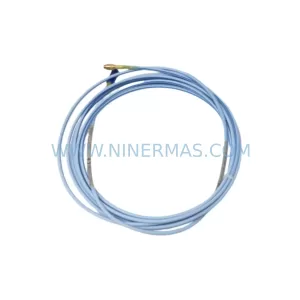
SKU: 330854-040-25-CN
Bently Nevada 330854-040-25-CN Safety Ruggedized Extension Cable
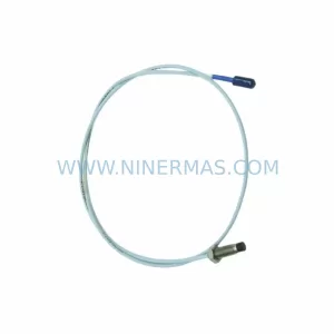
SKU: 330101-00-52-10-02-CN
Bently Nevada 330101-00-52-10-02-CN Service-Ready Spare Part
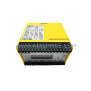
SKU: 21000-28-05-40-025-03-02
Bently Nevada 21000-28-05-40-025-03-02 Retrofit for 3300 XL