Original Industrial Spare Part
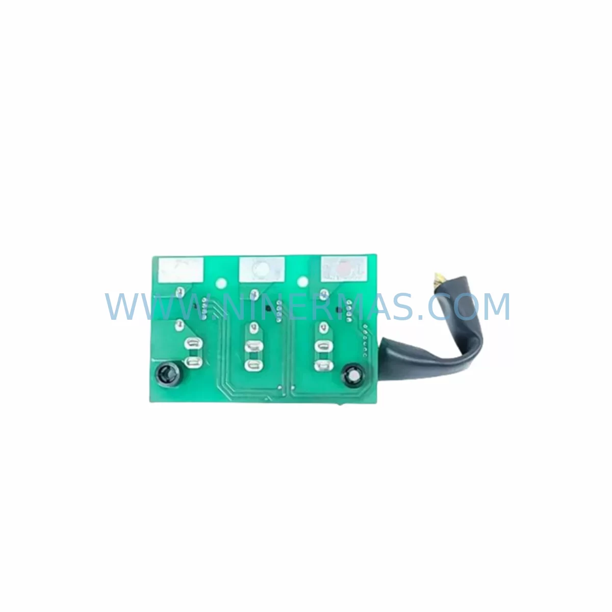
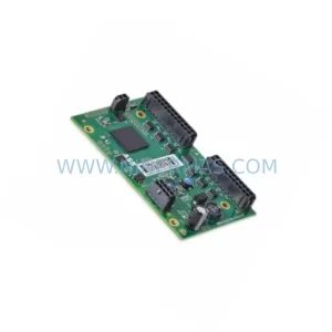
Yaskawa DESIG-3PCB Retrofit-Compatible Drive PCB for Legacy Systems
Verify the part, confirm the platform family, and move straight into quotation with the right commercial details.
RFQ Ready
- SKUDESIG 3PCB
- CategoryPLC & Industrial Automation Modules
- BrandYASKAWA
- SupportAvailability, lead time, condition, and shipping coordination
How Buyers Usually Use This Page
- Confirm the exact part number and platform family before sending the quote request.
- Use direct email when quantity, condition, and destination are already defined internally.
- Switch to the broader brand or category archive when you need alternates nearby.
Series Navigation
Move through the most common platform families behind this part.
Product RFQ
Send this part directly for quotation.
Include quantity, required condition, destination country, and target delivery timing. Current reference: Yaskawa DESIG-3PCB Retrofit-Compatible Drive PCB for Legacy Systems with SKU DESIG 3PCB.
Yaskawa DESIG-3PCB Retrofit-Compatible Drive PCB for Legacy Systems
The Yaskawa DESIG-3PCB is a retrofit-compatible drive control printed circuit board engineered to serve as a direct replacement for legacy Yaskawa variable frequency drive platforms, including the widely deployed VS-616G5 series. As industrial facilities face increasing pressure to maintain aging automation infrastructure without full system overhauls, the DESIG-3PCB provides a cost-effective, technically validated path to extend operational life, restore drive functionality, and reduce unplanned downtime. With a 12-month warranty and mandatory pre-shipment functional testing, this board is a trusted solution for maintenance engineers, system integrators, and procurement teams managing long-cycle industrial assets.
The DESIG-3PCB functions as the primary control board within the drive assembly, managing gate signal generation, fault detection, parameter storage, and communication interfacing. Its compatibility with legacy drive architectures makes it particularly valuable in environments where full drive replacement would require extensive rewiring, software reprogramming, or mechanical modifications to existing control cabinet layouts.
Upgrade Compatibility Table
| Parameter | Details |
|---|---|
| Compatible Drive Series | Yaskawa VS-616G5, VS-616G3, VS-606V7 (verify nameplate before ordering) |
| Board Function | Main drive control PCB — gate drive, fault logic, parameter memory |
| Mounting Interface | Direct board-level replacement; confirm standoff pattern and connector pitch |
| Communication Compatibility | Compatible with SI-N3/V PROFIBUS and SI-EN3/V Ethernet option cards where fitted |
| Power Supply Requirement | Internal 5 VDC / 15 VDC from drive SMPS; verify ETC740110-S0100 PSU output before installation |
| Terminal Wiring | Retain existing control wiring; verify TB1/TB2 terminal block assignments against original drawings |
| Parameter Backup | Back up all parameters via JVOP-100 digital operator or DriveWizard before board swap |
| Installation Space | Same form factor as original DESIG-3PCB; no cabinet modification required |
| Debugging Requirement | Re-enter or restore parameters; verify encoder feedback via PG-B3 card if vector control is used |
| Warranty | 12 months from shipment date, covering manufacturing defects under normal operating conditions |
Retrofit Planning for Existing Automation Systems
Successful integration of the DESIG-3PCB into a legacy drive system requires a structured pre-replacement assessment. Before removing the failed board, maintenance teams should document all existing parameter settings using the JVOP-100 digital operator or a laptop running DriveWizard software connected via a USB-to-RS422 programming cable. This step is critical to preserving motor tuning data, acceleration/deceleration ramp profiles, and fault history logs that may be required for post-installation verification.
The internal power supply module — typically the ETC740110-S0100 switching power supply board — should be tested for correct 5 VDC and 15 VDC rail outputs before the new DESIG-3PCB is installed. A degraded PSU is a common secondary cause of control board failure and must be ruled out to prevent repeat failures after replacement.
If the drive is configured for closed-loop vector control, the PG-B3 encoder feedback card must be inspected for secure seating and correct encoder signal levels. Encoder wiring integrity directly affects motor speed regulation and fault-free operation after the board swap. Similarly, if the installation uses a SI-N3/V PROFIBUS option card or a SI-EN3/V EtherNet/IP card for PLC communication, these cards should be removed before the board swap and reinstalled afterward, with network node addresses and baud rate settings re-confirmed at the PLC level.
For drives installed in multi-axis control cabinets, the DESIG-2PCB gate driver board and DESIG-1PCB interface board — where present — should be visually inspected for signs of thermal stress or capacitor bulging during the same maintenance window. Replacing only the DESIG-3PCB while leaving degraded ancillary boards in place increases the risk of secondary failures within weeks of restoration.
Terminal block wiring at TB1 and TB2 should be photographed and labeled before disconnection. Control signal wiring for analog speed reference inputs (0–10 VDC or 4–20 mA), digital run/stop commands, and fault relay outputs must be reconnected to the correct terminals on the replacement board. Wiring errors at this stage are a leading cause of commissioning delays and potential drive damage.
Where the drive interfaces with a legacy HMI panel using RS-485 Modbus RTU, the communication link should be tested using a protocol analyzer before and after the board swap to confirm that register mapping and baud rate settings are preserved. If the HMI screens reference drive fault codes or speed feedback values, these should be validated against the restored parameter set to ensure display accuracy.
For facilities managing multiple VS-616G5 drives across a production line, maintaining a reserved stock of DESIG-3PCB boards alongside compatible BC-2PCB base card assemblies and 73600-A0060 gate driver modules significantly reduces mean time to repair. A pre-tested spare board program, combined with documented parameter backup files stored on a shared network drive, enables board-level replacement within a single shift without requiring specialist drive technician support.
Downtime Control During System Migration
Minimizing production downtime during a DESIG-3PCB replacement requires advance preparation rather than reactive response. The most effective approach is to pre-stage a tested replacement board before the failed unit is removed from service. Each DESIG-3PCB shipped by NINERMAS undergoes a functional bench test prior to dispatch, confirming gate signal output, power rail integrity, and communication port operation. This pre-shipment verification reduces the risk of receiving a non-functional replacement and eliminates the need for on-site incoming inspection.
Parameter restoration is the most time-sensitive step in the replacement process. If a current parameter backup file exists — exported via JVOP-100 or DriveWizard — restoration takes less than ten minutes. Without a backup, parameters must be re-entered manually from the original commissioning documentation, which can extend downtime by several hours. Facilities without a parameter backup program should treat the DESIG-3PCB replacement as an opportunity to establish one.
Where the drive controls a critical process — such as a compressor, extruder, or conveyor in a continuous production environment — a temporary bypass using a manual starter or a portable variable frequency drive may be used to maintain partial production capacity while the primary drive is being serviced. This approach requires coordination with the process control team and must be documented in the site’s management of change procedure.
After the replacement board is installed and parameters are restored, a controlled no-load test run should be performed before reconnecting the driven load. Monitor output current, voltage balance across phases, and encoder feedback signal quality during the test run. Any fault codes generated during this phase should be investigated and resolved before returning the drive to full production service.
Retrofit Support FAQ
Q1: Is the DESIG-3PCB a direct drop-in replacement for the original board in my VS-616G5 drive?
In most cases, yes. The DESIG-3PCB is designed as a board-level replacement for the VS-616G5 control board assembly. However, drive firmware revisions and hardware variants across production years may affect compatibility. Provide your drive nameplate data — including model number, software version, and manufacturing date code — when placing your order so that compatibility can be confirmed before shipment.
Q2: What pre-shipment testing is performed on the DESIG-3PCB?
Every DESIG-3PCB unit is functionally tested on a compatible drive test bench before dispatch. Testing covers power rail verification, gate signal output integrity, fault detection logic, and communication port operation. A test report is available upon request. The board is covered by a 12-month warranty from the shipment date.
Q3: Do I need to re-enter all drive parameters after replacing the DESIG-3PCB?
Yes. The DESIG-3PCB does not retain parameter data from the failed board. All parameters must be restored from a backup file or re-entered manually. NINERMAS recommends backing up parameters using the JVOP-100 digital operator or DriveWizard software before any board-level maintenance. If you do not have a backup, contact our technical support team for assistance with parameter reconstruction from nameplate and application data.
Q4: What is the typical lead time and stock availability for the DESIG-3PCB?
NINERMAS maintains reserved inventory of the DESIG-3PCB to support urgent maintenance requirements. Standard lead time for in-stock units is 3–5 business days for international shipments. For facilities with multiple drives using this board, long-term supply agreements and reserved stock programs are available to guarantee availability and lock in pricing. Contact sale@ninermas.com for volume pricing and supply commitment options.
| Product Series | Legacy |
|---|---|
| Country of Origin | JP |
Catalog Continuation
More YASKAWA modules in the catalog.
Use the brand lane to compare nearby part numbers, platform-adjacent modules, and other inquiry-ready listings before sending your final RFQ.
SKU: DX100DX200 jZRCR-YPP01-1 JZRCR-YPP21-1 SRDA-SDB95A01A-E 10Y-06A DC-24V
Yaskawa JZRCR-YPP01-1 Retrofit-Compatible Pendant for Legacy Systems
SKU: YRC1000 JZRCR-APP01-1
Yaskawa JZRCR-APP01-1 Service-Ready Spare Part for Industrial Maintenance
SKU: YRK01B-1E DX100CPUJZNC-YRK01B-1E JANCD-ASF30-1E 50999-2922R07 CPU50999-2922R07
Yaskawa YRK01B-1E Retrofit-Compatible Servo Board for Legacy Systems
Catalog Continuation
Alternative parts within PLC & Industrial Automation Modules.
Stay inside the same system family when you need substitutes, adjacent modules, or a broader shortlist for procurement review.
SKU: C98043-A7007-L4 6RY1703-0FA04
SIEMENS C98043-A7007-L4 6RY1703-0FA04 Service-Ready Spare Part
SKU: DSQC643 3HAC024488-001/03
ABB 3HAC024488-001/03 DSQC643 Retrofit I/O Board for Legacy IRC5