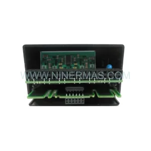
Original Industrial Spare Part
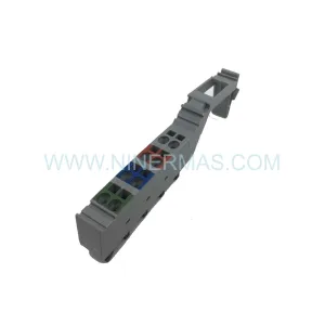
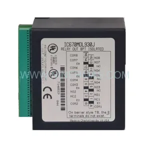
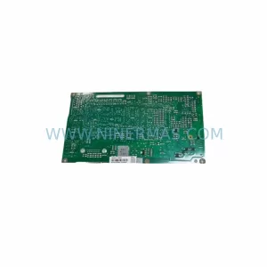
Fisher CL6721X1-A4 41B5215X132 Retrofit Positioner
Verify the part, confirm the platform family, and move straight into quotation with the right commercial details.
RFQ Ready
- SKUCL6721X1-A4 41B5215X132
- CategoryPLC & Industrial Automation Modules
- BrandFisher
- SupportAvailability, lead time, condition, and shipping coordination
How Buyers Usually Use This Page
- Confirm the exact part number and platform family before sending the quote request.
- Use direct email when quantity, condition, and destination are already defined internally.
- Switch to the broader brand or category archive when you need alternates nearby.
Series Navigation
Move through the most common platform families behind this part.
Product RFQ
Send this part directly for quotation.
Include quantity, required condition, destination country, and target delivery timing. Current reference: Fisher CL6721X1-A4 41B5215X132 Retrofit Positioner with SKU CL6721X1-A4 41B5215X132.
Fisher CL6721X1-A4 41B5215X132 Retrofit-Compatible Positioner for Legacy Control Valve Systems
The Fisher CL6721X1-A4 41B5215X132 is a pneumatic valve positioner engineered for the Fisher CL Series control valve platform — a workhorse of legacy process automation systems across oil & gas, chemical processing, power generation, and water treatment industries. As original Fisher CL Series components approach end-of-life and OEM support windows close, plant engineers and procurement teams are increasingly sourcing retrofit-compatible replacements to extend operational continuity without committing to full valve train overhauls.
NINERMAS supplies the Fisher CL6721X1-A4 41B5215X132 as a verified retrofit-compatible positioner unit, backed by a 12-month warranty and pre-shipment functional testing. Each unit is inspected against original Fisher dimensional and performance specifications, ensuring compatibility with existing CL Series valve bodies, yoke mounting configurations, and instrument air supply connections before it leaves our facility.
Upgrade Compatibility Table
| Parameter | Specification / Retrofit Note |
|---|---|
| Part Number | CL6721X1-A4 / 41B5215X132 |
| Brand / OEM | Fisher Controls (Emerson) |
| Product Series | CL Series Pneumatic Positioner |
| Mounting Interface | Fisher CL Series yoke / side-mount bracket — confirm yoke arm geometry before installation |
| Input Signal | 3–15 psi (0.2–1.0 bar) pneumatic input; verify against existing I/P transducer output |
| Supply Pressure | Typically 20–100 psi instrument air; confirm against existing supply header capacity |
| Communication Compatibility | Pneumatic signal loop; no HART/fieldbus — if digital migration is planned, pair with Fisher DVC6200 digital valve controller |
| Replacement Fit | Direct retrofit for legacy CL Series positioner assemblies; confirm feedback linkage pin dimensions |
| Commissioning Requirements | Zero/span calibration, bench set verification, split-range check if applicable |
| Installation Space | Confirm clearance for positioner body and tubing connections within existing control valve enclosure |
| Warranty | 12 Months — covers manufacturing defects and functional performance |
Retrofit Planning for Existing Automation Systems
Replacing a Fisher CL6721X1-A4 41B5215X132 in an operating plant requires a structured approach that goes well beyond simply swapping the positioner body. The first step is a thorough review of the existing instrument air supply capacity. Many aging control cabinets and valve skids were designed around instrument air headers that have since been extended or partially degraded. Before installation, verify that the supply pressure at the positioner inlet remains within the rated range under full-plant demand conditions — pressure drops during peak consumption cycles are a common cause of positioner instability after retrofit.
Terminal wiring and tubing connections are the next critical checkpoint. The CL6721X1-A4 uses a pneumatic signal input, so the associated I/P transducer — often a Fisher 546 or 546S electro-pneumatic transducer — must be confirmed as functional and correctly calibrated to deliver a clean 3–15 psi signal. If the existing I/P transducer is also at end-of-life, it is strongly recommended to replace both units simultaneously to avoid a second unplanned shutdown. Similarly, the instrument air filter-regulator upstream of the positioner — typically a Fisher 67CFR or equivalent — should be inspected and serviced as part of the same maintenance window.
Backplane and rack considerations apply when the CL Series valve is integrated into a broader DCS or PLC-based control loop. If the control signal originates from a legacy analog output card — such as those found in older Emerson DeltaV S-series I/O modules or Honeywell TDC 3000 analog output assemblies — confirm that the output card is still capable of delivering a stable 4–20 mA signal to the I/P transducer. Degraded analog output cards are frequently the root cause of positioner hunting or offset errors that are incorrectly attributed to the positioner itself.
For plants considering a partial migration toward digital valve management, the Fisher CL6721X1-A4 41B5215X132 can serve as a stable interim solution while HART-enabled infrastructure is being installed. In parallel loops, engineers often retain pneumatic positioners on non-critical valves while upgrading critical control valves to Fisher DVC6200 or DVC6000 digital valve controllers with HART 7 communication. This phased approach allows AMS Device Manager or equivalent valve diagnostic software to be introduced incrementally without disrupting the entire control loop architecture.
Feedback linkage geometry deserves particular attention during CL Series positioner retrofits. The feedback arm, cam profile, and linkage pin dimensions must match the original assembly to ensure accurate valve position feedback. Mismatched linkage geometry is a leading cause of non-linearity and hysteresis in retrofitted positioner installations. Where original Fisher linkage hardware is unavailable, confirm dimensional equivalence before installation. The valve stem travel range — whether 1 inch, 1.5 inch, or 2 inch — must also be matched to the positioner’s internal cam selection.
Control cabinet space planning is essential when the retrofit is part of a broader control panel upgrade. If the existing cabinet also houses a Fisher 4150 or 4160 pressure controller, a Fisher 2500 or 2503 controller, or legacy pneumatic relay assemblies, confirm that the new positioner’s tubing routing does not conflict with existing instrument runs. Adequate clearance for the positioner cover removal — required for zero/span adjustment — must be maintained in the installed position.
Downtime Control During System Migration
Minimizing unplanned downtime during a CL Series positioner replacement begins with pre-staging. The Fisher CL6721X1-A4 41B5215X132 should be bench-tested and pre-calibrated before the maintenance window opens. Bench calibration involves setting the zero and span adjustments to match the existing valve’s bench set range — typically confirmed from the original valve specification sheet or the as-found calibration record. This eliminates the need for extended on-valve calibration during the shutdown window.
Where the control loop cannot be taken fully offline, a partial bypass strategy using a manual handwheel operator or a bypass valve in the process line allows the positioner swap to proceed while maintaining process flow continuity. Confirm with the process safety team that the bypass arrangement is consistent with the plant’s process hazard analysis before proceeding.
Program logic protection is critical when the positioner replacement is accompanied by any changes to the DCS or PLC configuration. Before any loop modifications, export and archive the current loop configuration from the control system — whether that is a Emerson DeltaV module, a Rockwell Logix5000 routine, or a Siemens S7 function block. Retain the original analog scaling, PID tuning parameters, and alarm setpoints. After positioner installation and calibration, perform a step-response test to verify that the loop tuning remains stable with the new positioner’s dynamic characteristics.
Post-installation verification should include a full stroke test from 0% to 100% and back, confirmation of split-range operation if applicable, leak testing of all pneumatic connections, and a review of the positioner’s supply pressure gauge reading under steady-state conditions. Document the as-left calibration data and retain it in the plant’s instrument maintenance management system for future reference. NINERMAS provides a pre-shipment test report with each unit to support this documentation requirement.
Retrofit Support FAQ
Q1: Is the Fisher CL6721X1-A4 41B5215X132 a direct drop-in replacement for the original CL Series positioner?
In most CL Series installations, yes — the mounting interface, tubing connections, and feedback linkage geometry are consistent with the original Fisher CL positioner design. However, we recommend confirming the yoke arm configuration, feedback linkage pin dimensions, and valve stem travel range against the original valve specification sheet before installation. NINERMAS technical support can assist with compatibility verification based on your valve tag data.
Q2: What commissioning steps are required after installation?
After mechanical installation and pneumatic connection, the positioner requires zero and span calibration using the external adjustment screws. A bench set verification against the valve’s rated travel range should be performed, followed by a full stroke test and a split-range check if the valve is configured for split-range operation. If the positioner is paired with a Fisher 546 I/P transducer, confirm that the transducer output is correctly calibrated to the 3–15 psi range before final loop commissioning.
Q3: What does the 12-month warranty cover?
The 12-month warranty covers manufacturing defects and functional performance failures under normal operating conditions. Each unit shipped by NINERMAS undergoes pre-shipment functional testing, and a test report is included with the delivery documentation. Warranty claims are supported by NINERMAS directly — contact sale@ninermas.com with your order reference and a description of the observed fault.
Q4: What is the typical lead time and stock availability?
NINERMAS maintains inventory of Fisher CL Series positioner components to support urgent retrofit and breakdown maintenance requirements. Standard orders are processed within 1–3 business days. For large-quantity procurement or long-term spare parts program commitments, contact our sales team to discuss stock reservation and scheduled delivery arrangements. We support both spot purchases and annual blanket order programs for maintenance, repair, and operations (MRO) procurement teams.
| Product Series | Other series |
|---|---|
| Country of Origin | US |
Catalog Continuation
More Fisher modules in the catalog.
Use the brand lane to compare nearby part numbers, platform-adjacent modules, and other inquiry-ready listings before sending your final RFQ.
SKU: CL6741 41B7293X022 CL6741X1-A2
Fisher CL6741X1-A2 Safety-Reliable Valve Controller for Critical Control Sites
SKU: 01984-2518-0002
Fisher 01984-2518-0002 Retrofit I/O Module for Legacy Systems
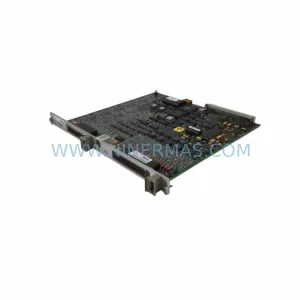
SKU: CL6827X1-A1 12P1392X042
Fisher CL6827X1-A1 12P1392X042 Retrofit SDI for Legacy Systems
Catalog Continuation
Alternative parts within PLC & Industrial Automation Modules.
Stay inside the same system family when you need substitutes, adjacent modules, or a broader shortlist for procurement review.
SKU: 6FC5357-0BB12-0AE0
Siemens 6FC5357-0BB12-0AE0 Service-Ready Industrial Spare Part
SKU: 3BSE011790R1(PXHK401)
ABB 3BSE011790R1 PXHK401 Retrofit-Ready Communication Module