Original Industrial Spare Part
GE Fanuc IC630MDL357A Retrofit-Compatible Output Module
Verify the part, confirm the platform family, and move straight into quotation with the right commercial details.
RFQ Ready
- SKUFANUC IC630MDL357A
- CategoryPLC & Industrial Automation Modules
- BrandGE Fanuc
- SupportAvailability, lead time, condition, and shipping coordination
How Buyers Usually Use This Page
- Confirm the exact part number and platform family before sending the quote request.
- Use direct email when quantity, condition, and destination are already defined internally.
- Switch to the broader brand or category archive when you need alternates nearby.
Series Navigation
Move through the most common platform families behind this part.
Product RFQ
Send this part directly for quotation.
Include quantity, required condition, destination country, and target delivery timing. Current reference: GE Fanuc IC630MDL357A Retrofit-Compatible Output Module with SKU FANUC IC630MDL357A.
GE Fanuc IC630MDL357A Retrofit-Compatible Output Module for Legacy IC630 Systems
The GE Fanuc IC630MDL357A is a discrete output module designed for the IC630 series programmable logic controller platform — one of the most widely deployed legacy control architectures in process manufacturing, material handling, and utility automation. As original IC630 hardware reaches end-of-life and spare parts become increasingly scarce, the IC630MDL357A remains a critical component for engineers tasked with maintaining uptime on aging control panels, extending the operational life of existing automation infrastructure, and executing phased migration strategies without full system replacement.
This module is stocked, pre-shipment tested, and backed by a 12-month warranty, making it a reliable choice for both emergency breakdown recovery and planned retrofit projects. Whether you are replacing a failed output card in a running production line or building out a retrofit kit for a scheduled shutdown window, the IC630MDL357A provides the output capacity and backplane compatibility required to restore control continuity with minimal engineering rework.
Upgrade Compatibility Table
| Parameter | Details |
|---|---|
| Model | GE Fanuc IC630MDL357A |
| Series | IC630 |
| Module Type | Discrete Output Module |
| Backplane Interface | IC630 Series Rack / Backplane Compatible |
| Installation Requirement | Standard IC630 rack slot; verify slot addressing before installation |
| Communication Compatibility | Native IC630 backplane bus; no protocol conversion required for same-series rack |
| Direct Replacement For | IC630MDL357 (earlier revision); verify output channel count and voltage rating |
| Cross-Series Upgrade Path | IC693 / IC695 series with I/O adapter or gateway module |
| Commissioning Focus | Module address configuration, output channel mapping, field wiring terminal verification |
| Pre-Shipment Testing | Yes — functional output verification performed before dispatch |
| Warranty | 12 Months |
Retrofit Planning for Existing Automation Systems
Successful integration of the IC630MDL357A into a legacy control panel begins well before the module arrives on site. Engineers should start by auditing the existing IC630 rack configuration — confirming available slot positions, verifying the rack’s power supply capacity (typically an IC630PWR321 or IC630PWR322 power supply unit), and documenting the current module address assignments to avoid address conflicts after installation.
Field wiring is one of the most time-sensitive steps in any output module replacement. The IC630MDL357A uses a standard terminal block interface; technicians should photograph or record the existing wiring layout from the failed module before removal. Output channel assignments must be cross-referenced against the PLC program logic — particularly any rung outputs tied to motor starters, solenoid valves, or pilot lights — to ensure the replacement module’s channel mapping matches the original configuration without requiring program edits.
For sites running mixed IC630 and IC693 hardware in the same control cabinet, the retrofit scope may extend to verifying communication between the IC630 CPU module and any IC693MDL series I/O modules connected via an expansion rack or remote I/O drop. In these environments, the IC630CMM321 communications module or equivalent gateway hardware may be involved in routing I/O data between rack segments. Confirming that the output module replacement does not disrupt existing I/O table mapping is essential before re-energizing the system.
Where the retrofit is part of a broader migration toward a Series 90-30 or PACSystems RX3i platform, the IC630MDL357A can serve as a bridge component — maintaining output functionality on the legacy rack while new IC694MDL series or IC695MDL series modules are staged in parallel. This parallel staging approach allows engineering teams to validate new I/O wiring and program logic against live process signals before committing to a full cutover, significantly reducing the risk of unplanned downtime.
HMI screen updates are another consideration during IC630 output module retrofits. If the existing operator interface — whether a legacy Quickpanel, a Series 90 HMI, or a third-party SCADA system — references specific output addresses or alarm bit assignments tied to the IC630MDL357A’s channel layout, those screen objects and alarm configurations must be reviewed and updated to reflect any address changes introduced during the retrofit. Failing to align HMI address references with the updated I/O configuration is a common source of post-commissioning faults.
Signal isolation requirements should also be assessed during retrofit planning. In applications where the IC630MDL357A drives inductive loads or interfaces with field devices operating at different voltage levels, signal isolators or interposing relays may be required to protect the module’s output transistors and ensure clean switching. Documenting these isolation requirements as part of the retrofit engineering package helps avoid field wiring errors during installation.
Downtime Control During System Migration
Minimizing production downtime during an IC630 output module replacement requires a structured pre-outage preparation process. Before the maintenance window opens, the site engineering team should export and archive the current PLC program from the IC630 CPU — using the appropriate programming cable and software version — to ensure a verified backup is available in the event of an unexpected fault during module swap. This backup should be stored both locally and off-site as a precaution.
During the outage window, the recommended sequence is: de-energize the rack, remove the failed IC630MDL357A, inspect the backplane connector for damage or contamination, seat the replacement module firmly, restore power, and verify module status indicators before re-enabling output channels from the CPU. If the rack uses a keyed slot configuration, confirm the replacement module’s key settings match the original before insertion.
For critical processes where even a brief output interruption is unacceptable, a hot-standby or redundant output strategy using a parallel IC630 rack segment may be appropriate. In these configurations, the standby rack’s output modules — potentially including additional IC630MDL357A units — can be switched into service while the primary module is replaced, maintaining field device control continuity throughout the maintenance operation.
Post-replacement commissioning should include a full output channel scan, verification of field device response to commanded outputs, and a review of the PLC’s fault log to confirm no residual errors remain from the failed module. Where the site uses a distributed control architecture with remote I/O racks connected via an IC630CMM or equivalent communications module, the communication link status should be confirmed as part of the post-commissioning checklist before returning the system to automatic operation.
Retrofit Support FAQ
Q: Is the IC630MDL357A a direct drop-in replacement for the IC630MDL357?
A: In most cases, yes. The IC630MDL357A is a revised version of the IC630MDL357 with the same form factor and backplane interface. However, engineers should verify output channel voltage ratings and any revision-specific wiring differences before installation, particularly in applications with tight output current margins.
Q: What commissioning steps are required after installing the IC630MDL357A?
A: After seating the module and restoring rack power, confirm the module’s slot address matches the original configuration in the PLC program. Perform a forced output test on each channel to verify field device response. Review the CPU fault log for any I/O configuration errors and clear any latched faults before returning the system to automatic mode.
Q: Can the IC630MDL357A be used in a rack alongside IC693 series modules?
A: The IC630MDL357A is designed for IC630 series racks and is not directly interchangeable with IC693 series slots. Mixed-series installations require appropriate rack adapters or gateway modules. For sites planning a full migration to IC693 or PACSystems hardware, the IC630MDL357A is best used as a short-term continuity solution while the new platform is staged and validated.
Q: What warranty and testing coverage is included?
A: Every IC630MDL357A unit shipped by NINERMAS undergoes pre-shipment functional testing to verify output channel operation before dispatch. All units are covered by a 12-month warranty against manufacturing defects and operational failure under normal use conditions. In-stock units are available for prompt dispatch to support emergency breakdown and planned maintenance schedules.
| Product Series | Fanuc |
|---|---|
| Country of Origin | US |
Catalog Continuation
More GE Fanuc modules in the catalog.
Use the brand lane to compare nearby part numbers, platform-adjacent modules, and other inquiry-ready listings before sending your final RFQ.
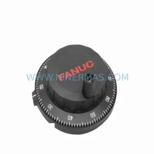
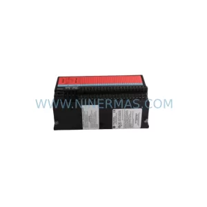
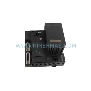
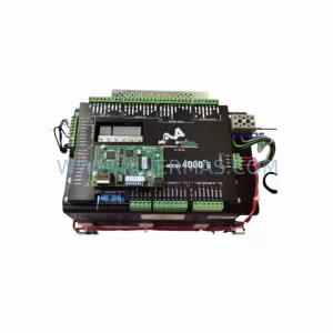
Catalog Continuation
Alternative parts within PLC & Industrial Automation Modules.
Stay inside the same system family when you need substitutes, adjacent modules, or a broader shortlist for procurement review.
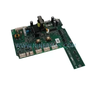
SKU: ZINT-541 3AUA00000658960
ABB ZINT-541 3AUA00000658960 Retrofit-Compatible Inverter Power Module
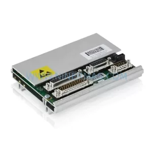
SKU: DSQC633 3HAC022286-001
ABB DSQC633 3HAC022286-001 Service-Ready Spare Part
SKU: 6SL3224-0BE33-7UA0
Siemens 6SL3224-0BE33-7UA0 Service-Ready Spare Part